Think about the smooth, instant acceleration of an electric car. Picture the precise, tireless movements of an industrial robot on an assembly line. Consider the clean energy flowing from solar panels into the grid. What makes these modern marvels possible? Deep inside the complex electronics, a powerful yet often unseen component is hard at work: the Insulated Gate Bipolar Transistor (IGBT). This remarkable semiconductor device acts as a high-speed, high-power switch, efficiently controlling the flow of electrical energy that drives countless applications integral to our daily lives and industries.
IGBTs (Insulated Gate Bipolar Transistors) are widely used as high-power electronic switches in applications requiring efficient control of electrical energy. Key applications include variable frequency drives (VFDs) for motor control, inverters for electric vehicles and renewable energy systems (solar, wind), uninterruptible power supplies (UPS), induction heating, and welding equipment. They bridge the gap between easy control and high power handling.
But the world of IGBTs goes far beyond simple switching. Understanding where and why they are used unlocks insights into the core of modern power electronics. This guide provides a deep dive into the diverse world of IGBT applications. We will explore exactly where and why these powerful semiconductor devices are deployed, how they function within different systems, and critically, why managing the significant heat they generate is absolutely essential for reliability – a challenge where expert thermal solutions become paramount. Let’s explore the applications that define our electric world.
What is an IGBT and Why is it Essential for Power Electronics?

An IGBT (Insulated Gate Bipolar Transistor) is a powerful semiconductor switch that combines the simple voltage control of a MOSFET with the high current capability of a Bipolar Junction Transistor (BJT). This unique hybrid design makes it essential for efficiently switching high voltages and currents at moderate speeds, forming the backbone of modern high-power electronic systems like motor drives, inverters, and power supplies. It offers a crucial balance of performance characteristics unavailable in other single device types.
The Best of Both Worlds: Combining MOSFET Speed and BJT Power
Think of the IGBT as a clever combination of two older transistor types:
- It has an “Insulated Gate” input structure just like a MOSFET. This means it can be turned on and off simply by applying a voltage to its gate terminal, requiring very little current. This makes it easy to control with simple, low-power drive circuits.
- Its output structure behaves like a Bipolar Junction Transistor (BJT). This allows it to handle much higher currents and block higher voltages than a similarly sized MOSFET.
By merging these features, the IGBT delivers the easy voltage control of a MOSFET along with the high power handling of a BJT, creating an almost ideal switch for many demanding applications.
How Does an IGBT Work as a Switch?
An IGBT has three main terminals: the Gate (G), the Collector (C), and the Emitter (E). Its operation as a switch is straightforward:
- OFF State: When no positive voltage (or a zero/negative voltage) is applied between the Gate and the Emitter, the switch is OFF. No significant current can flow between the Collector and the Emitter, even if there is a high voltage across them.
- ON State: When a sufficient positive voltage (typically +15V) is applied between the Gate and the Emitter, the switch turns ON. This allows a large current to flow from the Collector to the Emitter with very little voltage drop across the device (low on-state voltage, Vce(sat)).
By rapidly applying and removing the gate voltage (often thousands of times per second, a technique called Pulse Width Modulation or PWM), the IGBT can precisely control the amount of power flowing through a circuit.
Key Advantages of IGBTs in High-Power Applications
IGBTs have become dominant in many areas because they offer a compelling set of advantages:
- High Voltage Blocking Capability: They can withstand high voltages (600V to over 6500V) when in the OFF state.
- High Current Handling Capability: They can conduct large currents (tens to thousands of amps) when in the ON state.
- Low On-State Voltage Drop (Vce(sat)): This means less power is wasted as heat when the switch is conducting current, leading to higher efficiency.
- Relatively Fast Switching Speed: While not as fast as MOSFETs, IGBTs can switch much faster than older devices like Thyristors, enabling efficient operation at frequencies up to tens of kilohertz.
- Simple Gate Drive Requirements: Being voltage-controlled makes them easy and inexpensive to drive compared to current-controlled devices like BJTs.
IGBT vs. MOSFET vs. Thyristor: Understanding the Trade-offs
No single switch is perfect for every job. Engineers choose between IGBTs, Power MOSFETs, and Thyristors based on the specific voltage, current, and switching frequency requirements of the application.
Generally, MOSFETs excel at lower voltages (<600V) and very high switching frequencies (>100 kHz). Thyristors (like SCRs) dominate at very high voltages and currents but have slow switching speeds. IGBTs fill the crucial middle ground, offering the best balance for applications involving high voltages (600V-3300V+) and moderate switching frequencies (1 kHz – 50 kHz).
| Device Type | Typical Voltage Range | Typical Current Range | Switching Speed | Key Advantage | Key Limitation |
|---|---|---|---|---|---|
| IGBT | 600V – 6500V+ | 10A – 3000A+ | Medium (1-50 kHz) | High Power Density, Good Efficiency | Slower than MOSFET |
| Power MOSFET | < 1000V (Typically < 600V) | 1A – 300A+ | Very Fast (>100 kHz) | High Speed, Low Voltage Drop at Low V | Higher Losses at High Voltage |
| Thyristor (SCR/GTO) | 1000V – 12000V+ | 100A – 10000A+ | Very Slow (< 1 kHz) | Highest Voltage/Current Capability | Slow Speed, Complex Control (GTO) |
Where Are IGBTs Dominant? Core Application Areas
IGBTs are the dominant force in any application that requires efficiently controlling large amounts of electrical power. Their dominance spans across four main sectors: industrial automation (motor drives), transportation (electric vehicles), renewable energy (solar and wind), and high-power grid infrastructure (UPS and power supplies). In each of these areas, IGBTs perform the critical task of converting and conditioning electricity to make modern technology possible.
Industrial Motor Drives (VFDs & Servo Drives): Precision and Efficiency
This is the classic and largest application for IGBTs. Over 60% of all industrial electricity is consumed by electric motors. A Variable Frequency Drive (VFD) uses a set of six IGBTs in an inverter bridge to control the speed and torque of an AC motor. By precisely adjusting the frequency and voltage supplied to the motor, VFDs allow for:
- Massive Energy Savings: Instead of running a motor at full speed and using a mechanical valve to reduce output (like a tap), a VFD slows the motor itself, saving enormous amounts of energy.
- Precise Process Control: In applications like conveyors, pumps, fans, and robotics, IGBT-driven VFDs and servo drives allow for smooth acceleration, deceleration, and precise positioning.
The Thermal Challenge: In a VFD, the IGBT module is the primary source of heat. These drives are often placed in hot, dusty factory cabinets, making reliable heat dissipation critical. A failure due to overheating can shut down an entire production line, making high-reliability custom heat sinks an essential part of the design.
Electric Vehicles (EVs) and Hybrid Electric Vehicles (HEVs): Powering the Powertrain
The electric vehicle revolution is built on IGBTs. The single most important component in an EV’s powertrain, after the battery and motor, is the main traction inverter. This power module is responsible for converting the high-voltage DC power from the battery pack into three-phase AC power to drive the electric motor. IGBTs are the high-current switches that make this conversion happen, controlling the vehicle’s speed and acceleration.
They are also used in other key EV components, including:
- On-Board Chargers (OBC): Converting AC power from the grid to DC to charge the battery.
- DC-DC Converters: Stepping down the high voltage from the main battery (e.g., 400V or 800V) to 12V to power lights, infotainment, and other accessories.
The Thermal Challenge: The traction inverter handles hundreds of amps of current and generates intense, fluctuating heat. To keep the inverter compact and lightweight, simple air cooling is not an option. This application demands high-performance liquid cooling, using custom-designed **liquid cold plates** (like those from Walmate Thermal) to ensure the IGBTs remain at their optimal temperature, maximizing both performance and range.
Renewable Energy Systems: Connecting Green Power to the Grid
IGBTs are the crucial link between green energy sources and the power grid. They are essential for converting the “wild” electricity generated by solar panels and wind turbines into the clean, stable AC power we use.
- Solar Inverters: Solar panels produce DC power. IGBTs are used in the inverter to chop this DC into high-frequency pulses and then filter it to create a perfect sine-wave AC, synchronized with the grid.
- Wind Turbine Converters: A wind turbine’s speed varies with the wind, producing AC power at a variable frequency. IGBTs are used in an AC-DC-AC converter to change this to a stable 50/60 Hz grid frequency.
The Thermal Challenge: A single utility-scale solar or wind inverter can process megawatts of power. The resulting heat is immense. These systems are often located in remote, harsh environments with high ambient temperatures. Large, robust cooling systems, ranging from massive forced-air heat sink assemblies to industrial liquid cooling, are required to ensure 24/7 reliability.
Power Supplies and Grid Infrastructure
The stability of our entire electrical infrastructure relies on high-power IGBTs. Their most common application in this area is in Uninterruptible Power Supplies (UPS). For critical facilities like data centers, hospitals, and banks, a power outage is not an option. A UPS uses IGBTs in an inverter to instantly convert DC battery power into clean, stable AC power the moment the grid fails.
They are also used in Flexible AC Transmission Systems (FACTS) and HVDC (High-Voltage DC) transmission stations, where massive IGBT modules switch thousands of volts and amps to help stabilize the national grid and transmit power efficiently over long distances.
The Thermal Challenge: For a UPS, reliability is paramount. The cooling system must be designed for absolute dependability and long life, as these systems sit in standby for years but must work perfectly when needed. This often involves redundant fans and custom-engineered heat sinks.
Other Key High-Power Applications
The versatility of IGBTs extends even further:
- Induction Heating & Welding: IGBTs are used to create high-frequency, high-current AC to generate intense heat for melting metal or creating a welding arc.
- Medical Equipment: Powering the strong magnetic gradients in MRI machines and providing the high-voltage pulses for X-Ray and CT scanners.
- Traction: Long before EVs, IGBTs were perfected in electric trains, trams, and subways to control their powerful traction motors.
| Application Area | Key Function | Typical Voltage/Current | Critical Performance Need | Common Thermal Challenge |
|---|---|---|---|---|
| VFDs (Motor Drives) | Motor Speed Control | 400V – 690V / 10A – 1000A+ | Reliability, Efficiency | Heat in enclosed cabinets (Forced Air) |
| EV Inverters | Motor Speed Control | 400V – 800V / 300A – 800A+ | Power Density, Durability | High, fluctuating heat in a compact space (Liquid Cooling) |
| Solar Inverters | DC to AC Conversion | 600V – 1500V / 50A – 500A | High Efficiency, Reliability | High ambient heat, outdoor exposure (Air or Liquid) |
| UPS Systems | DC to AC Conversion | 480V – 600V / 100A – 2000A+ | 24/7 Reliability | Long-life, redundant forced-air cooling |
| Induction Heating | AC to AC Conversion (High Freq) | 600V – 1200V / 100A – 1000A | High Duty Cycle | Intense, localized heat (Often Liquid Cooling) |
Why is Efficient Cooling Critical for IGBT Applications?
Efficient cooling is absolutely critical for IGBT applications because heat is the primary enemy of power semiconductors. IGBTs generate significant heat as an unavoidable byproduct of switching high currents, and excessive temperatures directly degrade their performance, shorten their lifespan, and can lead to catastrophic failure. Therefore, thermal management isn’t just an accessory; it is an integral part of the IGBT system design necessary for achieving reliability and efficiency.
The Inevitable Byproduct: Heat Generation (Switching & Conduction Losses)
IGBTs, while efficient, are not perfect switches. They generate heat in two primary ways:
- Conduction Losses: When the IGBT is ON and conducting current, there is a small voltage drop across it (Vce(sat)). This voltage drop multiplied by the current flowing through it results in power dissipated as heat (P = Vce(sat) * Ic).
- Switching Losses: During the brief moments when the IGBT transitions between the ON and OFF states (and vice-versa), both voltage and current are present simultaneously. This generates a significant burst of heat. The faster the IGBT switches (higher frequency), the more often these switching losses occur, leading to higher overall heat generation.
In high-power applications, these losses can add up to hundreds or even thousands of watts of waste heat generated within a very small silicon chip.
How Does Temperature Affect IGBT Performance and Lifespan?
The operating temperature of an IGBT has a profound impact on its behavior and longevity:
- Reduced Efficiency: As temperature increases, the on-state voltage drop (Vce(sat)) typically rises, meaning conduction losses increase, and overall system efficiency decreases.
- Increased Failure Rates: Semiconductor failure rates increase exponentially with temperature. High temperatures accelerate degradation mechanisms within the chip and its packaging.
- Risk of Thermal Runaway: In some cases, increasing temperature can lead to increasing losses, which further increases temperature, creating a dangerous positive feedback loop that can destroy the device.
- Parameter Shifts: Key electrical characteristics, like switching speed, can change with temperature, potentially affecting system stability and control.
A general rule of thumb in electronics reliability is that for every 10°C increase in operating temperature above a certain baseline, the expected lifespan of a semiconductor device is halved. Keeping IGBTs cool is directly linked to making them last longer.
The Direct Link Between Thermal Management and System Reliability
Because temperature is so critical, the thermal management system (the heat sink or liquid cold plate) is not just a passive add-on; it is an active enabler of IGBT performance and reliability. A well-designed cooling solution ensures the IGBT operates within its safe temperature limits under all expected load conditions.
Failing to provide adequate cooling is designing for failure. It guarantees reduced performance, shortened lifespan, and increases the likelihood of unexpected system downtime, which can be extremely costly in industrial, automotive, or grid applications. Investing in a high-quality, properly engineered thermal solution is investing in the overall reliability of the entire system.
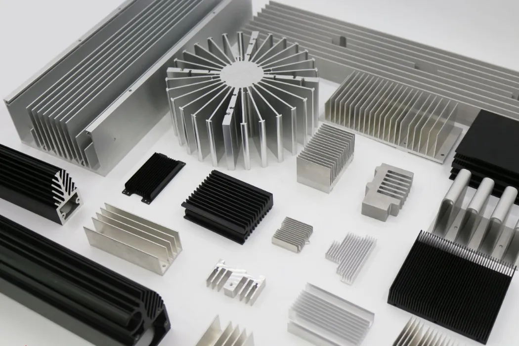
Common Cooling Strategies for IGBT Modules (Air vs. Liquid)
The choice of cooling strategy depends heavily on the power level and thermal density of the IGBT application:
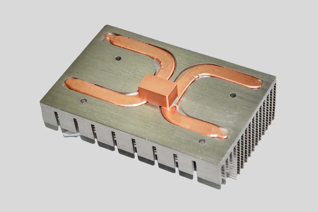
- Air Cooling: For lower-power IGBT modules (up to a few kilowatts), a well-designed heat sink with forced airflow (using fans) is often sufficient. This involves mounting the IGBT module onto a large aluminum or copper heat sink designed to maximize surface area.
- Liquid Cooling: For high-power modules (tens to hundreds of kilowatts), particularly in compact spaces like EV inverters, air cooling becomes impractical. Here, liquid cold plates are essential. The IGBT module is mounted directly onto a cold plate through which a coolant flows, offering far superior heat removal capacity.
Expert thermal partners like Walmate Thermal specialize in designing and manufacturing both high-performance heat sinks and custom liquid cold plates tailored specifically for demanding IGBT applications.
How Are IGBTs Selected for Specific Applications?
Selecting the right IGBT for a specific application is a critical engineering task that goes beyond simply matching voltage and current ratings. Engineers must carefully analyze the device’s datasheet, considering parameters like switching speed, on-state voltage, and thermal characteristics. Furthermore, the choice between discrete IGBTs and integrated power modules, along with careful consideration of the operating frequency, directly impacts system performance, cost, and reliability.
Key Datasheet Parameters Engineers Must Consider
When comparing IGBT options, engineers focus on several key parameters found in the datasheet:
- Collector-Emitter Voltage (Vces): This is the maximum voltage the IGBT can block when it is OFF. It must be chosen with a significant safety margin above the application’s maximum operating voltage (often 1.5x to 2x).
- Continuous Collector Current (Ic): This rating indicates the maximum continuous DC current the IGBT can handle at a specified case temperature (e.g., 25°C or 100°C). Real-world operating current should be kept well below this limit.
- Switching Speeds (tr, tf, Eon, Eoff): These parameters (rise time, fall time, turn-on energy, turn-off energy) dictate how quickly the IGBT can switch and determine the switching losses. Faster switching generally means lower losses but can cause electromagnetic interference (EMI) issues.
- On-State Voltage Drop (Vce(sat)): This is the voltage across the IGBT when it is fully ON and conducting current. A lower Vce(sat) means lower conduction losses and higher efficiency.
- Thermal Resistance (RthJC): This crucial parameter defines how effectively heat can travel from the internal silicon chip (Junction) to the device’s outer case (Case). A lower RthJC indicates better internal heat transfer.
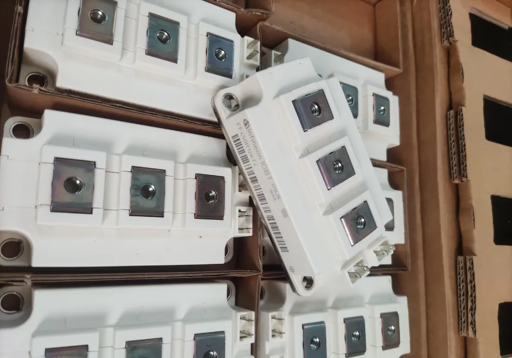
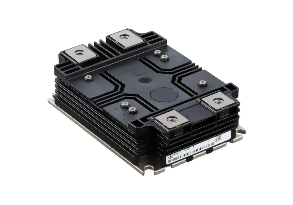
Understanding IGBT Module Packaging (Discrete vs. Module)
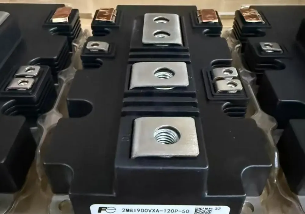
IGBTs come in various physical packages:
- Discrete IGBTs: These are single IGBT chips housed in standard transistor packages (like TO-247). They are suitable for lower power applications or designs where flexibility is needed. However, assembling multiple discrete devices for higher power can be complex.
- IGBT Modules: These integrate multiple IGBT chips (often along with anti-parallel diodes) into a single, larger package with a flat baseplate designed for easy mounting onto a heat sink or cold plate. Modules simplify the design of high-power converters (like the six IGBTs needed for a VFD) and offer better thermal performance due to the integrated baseplate.
The choice depends on the power level, assembly complexity, and thermal management strategy.
Matching the IGBT to the Switching Frequency and Power Level
There’s an inherent trade-off in IGBT design between switching speed and on-state voltage. IGBTs designed for lower frequencies (like motor drives operating at 5-15 kHz) are optimized for low Vce(sat) to minimize conduction losses. IGBTs designed for higher frequencies (like power supplies operating at 20-50 kHz) are optimized for faster switching speeds to minimize switching losses.
Engineers must select an IGBT family that is specifically suited for the target switching frequency and power level of their application to achieve maximum efficiency.
The Importance of Simulation (Electrical & Thermal) in Selection
Datasheets provide crucial information, but they don’t tell the whole story. Real-world performance depends heavily on the specific operating conditions (voltage, current, frequency, temperature) and the surrounding circuit.
Before finalizing an IGBT selection, engineers increasingly rely on **simulation tools**. Electrical simulation (like SPICE) helps predict switching waveforms and losses. Crucially, **thermal simulation (CFD)**, a core expertise at Walmate Thermal, models the heat flow from the IGBT chip, through its package, and into the cooling system. This ensures the chosen IGBT will operate within safe temperature limits under the application’s specific load profile, preventing costly failures down the line.
What Are the Future Trends in IGBT Applications and Technology?
The world of power electronics is constantly evolving, and while IGBTs remain dominant, future trends point towards increasing competition from new materials, greater integration, and an ever-growing emphasis on efficiency and power density. Understanding these trends is crucial for engineers planning next-generation systems. The constant push for more power in smaller spaces also means that advanced thermal management will become even more critical.
The Rise of Wide-Bandgap (WBG) Competitors (SiC & GaN)
The most significant trend impacting IGBTs is the emergence of wide-bandgap semiconductors, primarily Silicon Carbide (SiC) and Gallium Nitride (GaN). These materials offer several advantages over traditional silicon:
- Higher Switching Frequencies: SiC and GaN devices can switch much faster than IGBTs, enabling smaller and lighter passive components (inductors, capacitors) and potentially higher system efficiency.
- Higher Operating Temperatures: They can tolerate significantly higher junction temperatures, sometimes simplifying cooling requirements.
- Lower On-State Resistance (especially SiC MOSFETs): This leads to lower conduction losses, particularly beneficial in applications like electric vehicles.
However, IGBTs still hold key advantages, particularly in very high voltage applications (>1200V) and in terms of cost-effectiveness and proven reliability. For many mainstream industrial and power applications, IGBTs remain the pragmatic choice, while SiC is rapidly gaining ground in performance-driven sectors like EVs.
Advancements in IGBT Chip Technology (e.g., Trench Field Stop)
IGBT technology itself is not standing still. Manufacturers are continuously improving chip designs to enhance performance. Modern IGBTs often feature sophisticated structures like Trench Gates and Field Stop (FS) layers. These advancements lead to:
- Lower Vce(sat) for reduced conduction losses.
- Faster switching speeds and reduced switching losses.
- Improved robustness and reliability.
These incremental improvements ensure that silicon IGBTs remain competitive against WBG devices in many application segments.
Integration and Intelligent Power Modules (IPMs)
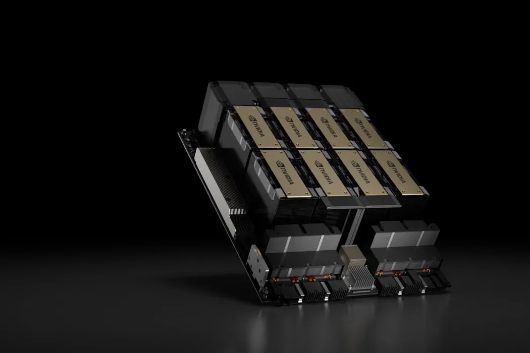
Another strong trend is towards greater integration. Instead of using discrete IGBTs, designers are increasingly opting for Intelligent Power Modules (IPMs). An IPM combines the IGBT power switches, their associated freewheeling diodes, and the gate driver circuitry (including protection features like over-current and over-temperature detection) into a single, optimized package.
IPMs simplify system design, reduce component count, improve reliability, and often offer better thermal performance due to the integrated structure designed for optimal heat spreading to a heat sink or cold plate.
Increasing Power Density and the Growing Need for Advanced Cooling
Regardless of whether the switch is an advanced IGBT, an IPM, or a SiC MOSFET, the overarching trend is towards **packing more power into smaller spaces**. This relentless drive for higher power density means that managing the resulting waste heat becomes an ever-greater challenge.
As power densities climb, traditional air cooling solutions become less viable. The future belongs to more efficient and compact thermal technologies like high-performance heat sinks with embedded heat pipes and, increasingly, direct liquid cooling using custom cold plates. Expert thermal design and manufacturing, like that provided by Walmate Thermal, is no longer an afterthought but a critical enabler for future power electronic systems.
| Feature | IGBT (Silicon) | SiC MOSFET |
|---|---|---|
| Voltage Range | Dominant >1200V, up to 6.5kV+ | Strong 650V-1700V, emerging >3.3kV |
| Switching Frequency Capability | Moderate (up to ~50 kHz) | High (100s of kHz) |
| On-State Resistance | Low Vce(sat) (Voltage Drop) | Very Low Rds(on) (Resistance) |
| Cost | Lower | Higher (but decreasing) |
| Maturity | Very High (Proven) | High (Rapidly Growing) |
| Typical High-Power Application Niche | Industrial Drives, High Voltage Grid | EV Inverters, High-Efficiency Power Supplies |
Frequently Asked Questions (FAQs)
1. What does IGBT stand for?
IGBT stands for Insulated Gate Bipolar Transistor. The name reflects its hybrid nature, combining an insulated gate (like a MOSFET) for easy control with a bipolar transistor structure (like a BJT) for high power handling.
2. Is an IGBT AC or DC?
An IGBT itself is a DC switch. It controls the flow of direct current between its collector and emitter. However, IGBTs are most commonly used in circuits like inverters and converters to create or control AC waveforms by rapidly switching the DC on and off.
3. What is the main function of an IGBT in an inverter?
In an inverter (like those used in VFDs, solar systems, or EVs), the main function of the IGBTs is to act as high-speed switches that “chop” a DC voltage into a series of pulses. By controlling the timing and width of these pulses (using PWM), the inverter can synthesize an AC waveform of the desired voltage and frequency.
4. Why do IGBTs fail?
The most common cause of IGBT failure is overheating. Excessive junction temperatures, often due to inadequate cooling, accelerate degradation and can lead to thermal runaway. Other causes include overvoltage, overcurrent, and mechanical stress or vibration leading to bond wire fatigue or solder joint cracking.
5. Can I replace a MOSFET with an IGBT?
Generally, no, not directly. While both are switches, they have different characteristics (voltage drop vs. resistance, switching speeds, gate drive needs). Replacing one with the other usually requires significant circuit redesign. IGBTs are typically used for higher voltage/power applications than MOSFETs.
6. What voltage levels are typical for IGBT applications?
IGBTs excel in medium to high voltage applications. Common voltage ratings range from 600V and 1200V for industrial drives and EVs, up to 1700V, 3300V, and even 6500V for high-power grid, traction, and industrial applications.
7. How do you test an IGBT module?
Testing involves several steps: static tests (checking for shorts/opens, measuring gate threshold voltage and leakage currents) and dynamic tests (measuring switching characteristics like rise/fall times and energy losses under load). Specialized curve tracers and double-pulse testers are often used.
8. What is the difference between an IGBT and an IPM (Intelligent Power Module)?
An IGBT is a single semiconductor component (or multiple chips in a basic module). An IPM integrates the IGBT power switches with their gate driver circuitry and often includes protection functions (like over-current, short-circuit, over-temperature) within a single package, simplifying design and improving reliability.
9. How important is the heat sink or cold plate for an IGBT module?
It is absolutely critical. The heat sink or cold plate is responsible for removing the waste heat generated by the IGBT. Without an effective thermal solution, the IGBT will quickly overheat and fail. The performance and reliability of any high-power IGBT system is directly dependent on the quality of its cooling system, making partners like Walmate Thermal essential.
Conclusion: Enabling High-Power Innovation, Reliably
From the heart of industrial automation to the powertrain of electric vehicles and the backbone of the renewable energy grid, Insulated Gate Bipolar Transistors are the indispensable workhorses enabling the efficient control of high-power electricity. Their unique blend of voltage control and current handling capabilities has made them central to countless technological advancements that shape our modern world. As we’ve explored their diverse applications, one common thread emerges: harnessing the full potential of IGBTs hinges entirely on effectively managing the significant heat they generate.
Optimal performance, long-term reliability, and the safety of any high-power IGBT system are inseparable from its thermal management strategy. An off-the-shelf cooling solution is often insufficient for the demanding, and often unique, operating conditions these devices face. True success requires a solution engineered for the specific application – a custom thermal design validated by simulation and proven through rigorous testing.
Don’t let thermal challenges compromise your high-power designs.
Walmate Thermal provides expert thermal solutions specifically designed for demanding IGBT applications. From custom heat sinks optimized for harsh industrial environments to high-performance liquid cold plates for compact EV inverters, our engineering team uses advanced simulation and manufacturing techniques (like FSW and vacuum brazing) to ensure your IGBTs operate coolly and reliably.Contact us today to discuss your IGBT cooling requirements. Let’s engineer a thermal solution that guarantees the performance and longevity of your power electronic systems.