How to Design a Liquid Cooling Plate?
1、 Clearly define design requirements
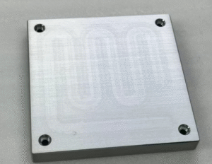
Before designing a liquid cooled plate, it is necessary to clarify its application scenarios and specific requirements. For example, if designing a liquid cooling plate for electronic chip heat dissipation, it is necessary to understand the chip’s power consumption, heat generation, operating ambient temperature, maximum allowable operating temperature for chip junction temperature, composition of coolant, inlet temperature of coolant, flow rate of coolant, and other parameters. If it is used for heat dissipation of new energy vehicle batteries, the layout of the battery pack, the heat generation characteristics during charging and discharging, and the operating temperature range should be considered. In addition, attention should be paid to factors such as installation space limitations, cost budget, reliability of the production process for liquid cooled plates, and compatibility with other systems.This article discusses the production and processing of flow channels based on integrated cold plates. The design scheme for the process of adding tube copper and aluminum plates will be discussed again in the future. So how to design a liquid cooling plate?
2、Choose appropriate materials
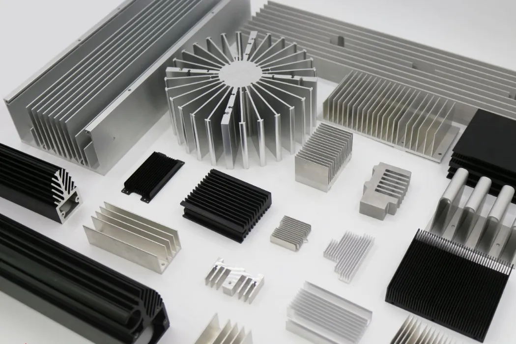
Aluminum alloy 6063 or 6061 is a commonly used metal material for liquid cooled plates due to its low density, good thermal conductivity (pure aluminum has a thermal conductivity of about 237W/(m · K), while aluminum alloy has a thermal conductivity between 180-230W/(m · K) depending on its composition), moderate strength, ease of processing and molding, and relatively low cost. The thermal conductivity of aluminum ADC12 produced by die-casting process is 90-110W/(m · K), which is characterized by simple process and low cost. Copper material has superior thermal conductivity (with a thermal conductivity of about 401W/(m · K)), but it has a higher density and higher cost. It can be selected when the heat dissipation requirements are extremely high and space and cost permit.
3、 Design flow channel structure
(1) Flow channel form
Common forms of flow channels include parallel channels, serpentine channels, and forked channels. Parallel flow channels have a simple structure and relatively low fluid flow resistance, making them suitable for heat sources with a relatively uniform distribution of heat flux density; Serpentine flow channels can increase the residence time of fluids in liquid cooled plates, improve heat transfer efficiency, but have higher flow resistance; Fork finger channels can distribute fluid more evenly to various areas, and have a better heat dissipation effect on non-uniform heat sources.
(2) Channel size
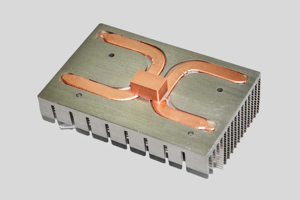
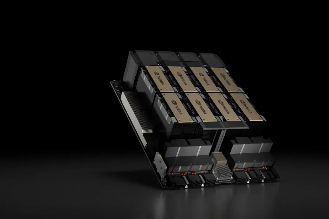
The width, height, and spacing of the flow channel have a significant impact on the heat dissipation performance of the liquid cooling plate. A smaller channel size can increase the contact area between the fluid and the channel wall, improve heat transfer efficiency, but it will increase flow resistance and pump power consumption. Generally speaking, the width of the flow channel can be selected between 6-15mm, the height between 2-10mm, and the spacing between the flow channels is determined according to actual needs and manufacturing processes. For chips with high power density that require small local contact area but high heat transfer in liquid cooled plates, microchannel design is needed for the local flow channels. For example, Nvidia’s GB200 GPU chip has a contact area of about 50X50mm, and its liquid cooled flow channels require high-density copper fins for heat exchange.
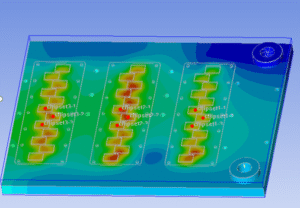
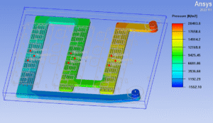
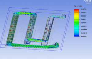
4、 Thermal analysis and simulation optimization
Use professional thermal analysis software such as ANSYS Fluent to perform numerical simulations on the designed liquid cooled plate. Input the heat load of the heat source, physical parameters of the fluid (such as density, specific heat capacity, thermal conductivity, etc.), flow boundary conditions (such as flow rate, flow velocity, etc.), simulate the temperature distribution and fluid flow characteristics inside the liquid cooling plate. Through simulation analysis, problems such as hot spots and uneven flow in the design can be identified, and the structure of the liquid cooling plate can be optimized, such as adjusting the shape of the flow channel and changing the position of the inlet and outlet, to achieve better heat dissipation effect.
5、 Manufacturing process selection
(1) Brazing liquid cooling plate process
For aluminum alloy liquid cooled plates, brazing is a commonly used manufacturing process. By placing brazing material between the sheets and melting it at a certain temperature and pressure, the sheets are connected together to form a flow channel structure. Vacuum brazing can ensure welding quality and reduce defects such as oxidation and porosity. The materials for vacuum brazing are generally divided into two types: all aluminum and all copper,
Aluminum silicon based brazing materials (such as Al Si alloy, with a melting point of about 577-615 ℃) are commonly used for all aluminum vacuum brazing. The brazing temperature is usually set at 580-620 ℃, slightly higher than the melting point of the brazing materials. Due to being carried out in a vacuum environment, there is no need for additional protective gas. Vacuum can prevent aluminum oxidation while promoting solder wetting and diffusion bonding.
Copper phosphorus or copper silver brazing materials are commonly used for all copper vacuum brazing (such as Cu-P alloy with a melting point of about 710-800 ℃), and the brazing temperature is about 750-900 ℃. Although it is a vacuum environment, some processes will introduce high-purity nitrogen gas (purity ≥ 99.99%) as a protective gas to further suppress copper oxidation and ensure the reliability of welding.
2) Friction Stir Welding
Friction stir welding is a solid-state bonding process, in which the stirring head rotates and moves along the interface to be welded, causing plastic deformation of the material and achieving bonding. This process has high welding strength and a small heat affected zone, making it suitable for manufacturing high-quality liquid cooled plates. Friction stir welding generates heat by rotating the stirring head to plasticize the material, and the plasticization temperature of aluminum alloy is usually between 300-500 ℃. The welding pressure is generally 10-50kN, which increases with the increase of material thickness. The stirring head speed is mostly 800-3000rpm, and the welding speed is 0.5-5mm/s. This process is solid-phase bonding, without melting defects, and is suitable for efficient bonding of non-ferrous metals such as aluminum and copper.
6、 Performance testing and validation
After manufacturing the liquid cooled plate sample, performance testing is required. Use temperature sensors to measure temperature at different locations, and monitor fluid flow and pressure drop through flow meters and pressure sensors. Compare the test results with the design requirements to evaluate whether the heat dissipation performance and flow resistance of the liquid cooled plate meet the requirements. If not met, analyze the reasons and further improve the design and manufacturing process.Designing a liquid cooled plate requires comprehensive consideration of multiple aspects such as requirements, materials, flow channel structure, thermal analysis, manufacturing process, and performance testing. Through continuous optimization and verification, high-quality liquid cooled plates that meet practical application requirements can be obtained.
Design and Dimension Scheme of Liquid Cooling Plate for 1kW Heat Source (Theoretical Calculation Case)
II. Theoretical Calculation of Key Parameters
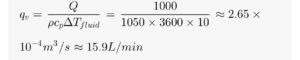
1. Calculation of Cooling Liquid Flow Rate
Based on the heat balance equation Q = \rho q_v c_p \Delta T_{fluid} , assuming the temperature difference between the inlet and outlet of the cooling liquid \Delta T_{fluid} = 10℃ (to avoid local overheating), the required flow rate is:
2. Design of Flow Channels and Flow Velocity
Multi-parallel flow channels are adopted (to reduce resistance). The size of a single flow channel: width w = 5mm = 0.005m , height h = 4mm = 0.004m . The hydraulic diameter is:
![]()
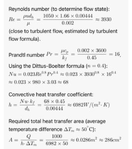
3. Calculation of Heat Transfer Coefficient and Area
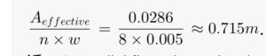
IV. Verification and Adjustment
According to this dimension, simulation verification shows that under a flow rate of 15.9L/min, the convective heat transfer resistance is about 0.05℃/W , the surface temperature of the heat source is stable at 80℃, and the pressure drop is ≤0.2MPa, meeting the 1kW heat dissipation requirement. If space is limited, the width can be reduced to 100mm and the length increased to 180mm to maintain the total heat transfer area unchanged.