Here is a powerful fact: over 50% of all electronic failures are caused by excessive heat. In a world where we demand more power from smaller devices, the humble heat sink is no longer an accessory—it’s the single most critical component for product reliability and performance. From the smallest chip on a circuit board to a massive data center processor, managing heat is the key to unlocking innovation, and the heat sink is the frontline defense.
A heat sink is a passive heat exchanger designed to absorb and dissipate heat from a hot electronic component (like a CPU or power transistor) into a surrounding fluid medium (usually air). It works by increasing the available surface area for heat transfer, primarily through conduction and convection, thus preventing the component from overheating and ensuring optimal performance and longevity.
But this is not just a guide on “what a heat sink is.” This is a complete engineer’s framework. We will go deep into heat sink design factors, explore the critical differences between manufacturing types, and provide a step-by-step guide for calculating and choosing the right one for your specific component—from a tiny TO-220 transistor to a high-performance M.2 SSD. Finally, we will show you how to source the perfect solution for your project, whether it’s a standard part or a fully custom-engineered assembly.
What is a Heat Sink & How Does it Work? The Fundamentals
A heat sink’s function is to prevent a component from overheating by moving thermal energy away from it as efficiently as possible. It is a passive device, meaning it has no moving parts and requires no power to operate, making it an incredibly reliable solution. It bridges the gap between a high-concentration heat source and the surrounding cooler environment, typically air. Without it, a modern processor would destroy itself from its own heat in under 10 seconds.
The Purpose: Why Do You Need a Heat Sink?
Every electronic component, from a CPU to an LED, generates waste heat as a byproduct of its operation. A tiny silicon chip (the “die”) might be only 150 mm², but it can generate over 200 watts of heat. This creates an incredibly high “heat flux” or heat density. Left alone, the chip’s temperature would skyrocket past its maximum junction temperature (Tj), which is often around 100°C to 150°C.
The heat sink’s purpose is to draw that concentrated heat out and “spread” it over a much larger surface area, allowing it to be safely dissipated into the air. It keeps the component’s temperature well below its failure point, ensuring:
- Performance: Prevents “thermal throttling,” where a chip slows itself down to avoid overheating.
- Reliability: Reduces thermal stress on the component.
- Longevity: A common rule of thumb is that for every 10°C (18°F) reduction in operating temperature, the lifespan of an electronic component is roughly doubled.
The Core Principles: How a Heat Sink Works
A heat sink works by using two fundamental principles of heat transfer in sequence:
- Conduction: First, heat is transferred from the hot component into the heat sink’s base through direct contact. This process, known as conduction, moves thermal energy through solid materials. This is why heat sinks are made of highly conductive metals like aluminum or copper.
- Convection: Once the heat has spread from the base to the fins, it must be transferred to the surrounding air. This is convection. The fins are designed to have a massive surface area. Air molecules touch the hot fins, absorb heat, become less dense, and naturally rise (this is “natural convection”). Colder, denser air then flows in to take its place, creating a slow, continuous cooling cycle.
- Radiation: A third, less dominant principle is thermal radiation. The heat sink’s surface emits thermal energy as infrared waves, just like a hot fireplace. This effect is most significant in passive, natural convection systems and can be enhanced by anodizing the heat sink black.
Key Components of a Thermal Solution
A heat sink never works alone. A complete thermal solution consists of several key parts:
- The Heat Source: The component generating heat (e.g., CPU, MOSFET, LED).
- The Thermal Interface Material (TIM): A critical, often-overlooked paste or pad that fills microscopic air gaps between the component and the heat sink. Air is a terrible conductor, and a good TIM can improve performance by 20-30%.
- The Heat Sink: The device itself, composed of a base (for conduction) and fins (for convection).
- The Fluid Medium (Air): The final destination for the heat. The temperature and flow rate of the air (natural or forced by a fan) dictates the system’s final performance.
What Are Heat Sinks Made Of? A Material Deep Dive
A heat sink’s performance is fundamentally limited by the material it’s made from. The choice involves a critical trade-off between thermal conductivity (performance), weight (density), and cost. While exotic materials exist, the vast majority of all heat sinks are made from two primary metals: aluminum and copper. The most common answer to “what is a heat sink made of?” is, overwhelmingly, an aluminum alloy.
Aluminum (e.g., Alloys 6061 & 6063): The Industry Standard
Aluminum is the go-to material for over 90% of heat sinks, and for good reason. It offers the best all-around balance of cost, weight, and performance. The most common alloys used are:
- Aluminum 6063: This is the most popular choice, especially for extruded heat sinks. It has good thermal conductivity (around 201 W/m·K), is lightweight, and its properties are excellent for the extrusion process, allowing complex fin shapes to be created easily and cost-effectively.
- Aluminum 6061: This alloy has slightly lower thermal conductivity (around 167 W/m·K) but offers superior mechanical strength. It’s often chosen for applications where the heat sink is also a structural component or needs to withstand vibration.
Aluminum’s low density (around 2.7 g/cm³) also makes it the default choice for large heat sinks where a solid copper equivalent would be impractically heavy.
Copper: The High-Performance Conductor
When raw performance is the absolute top priority, engineers turn to copper. With a thermal conductivity of around 385 W/m·K, copper is nearly twice as effective at conducting heat as 6063 aluminum. This makes it exceptional at absorbing heat from a small, concentrated source (like a CPU die) and spreading it quickly across the base of the heat sink.
However, this performance comes with two significant trade-offs: cost and weight. Copper is far more expensive than aluminum, and with a density of 8.96 g/cm³, it is over 3 times heavier. A large, solid-copper heat sink can be prohibitively heavy and expensive for most applications.
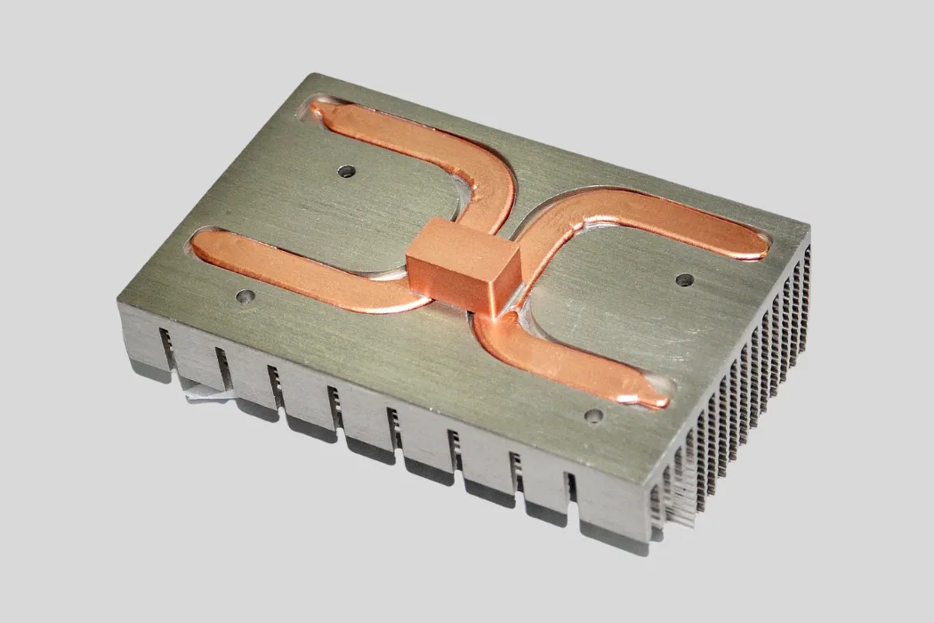
Hybrid Designs: Copper Base with Aluminum Fins
The most common high-performance solution is a hybrid approach that leverages the best of both materials. This design features:
- A solid copper base that sits directly on the hot component, using copper’s superior conductivity to absorb the high-density heat flux.
- Aluminum fins that are bonded, brazed, or press-fit onto the copper base. The heat efficiently transfers from the copper to the aluminum, which then dissipates it to the air.
This method gives you the high-performance heat absorption of copper while keeping the overall weight and cost down by using lightweight aluminum for the fins.
Other Materials (e.g., Graphite, Composites)
For niche, cutting-edge applications, engineers are exploring advanced materials. Annealed pyrolytic graphite (APG), for example, is a synthetic material with a thermal conductivity of up to 1,500 W/m·K in-plane. It is extremely lightweight and is used in aerospace and high-end mobile devices to spread heat laterally, though its cost is very high.
| Material | Thermal Conductivity (W/m·K) | Density (g/cm³) | Relative Cost | Key Pro | Key Con |
|---|---|---|---|---|---|
| Aluminum (6063) | ~201 | 2.70 | $ | Best all-around balance, easy to extrude | Lower conductivity than copper |
| Aluminum (6061) | ~167 | 2.70 | $ | Better mechanical strength | Worse conductivity than 6063 |
| Copper (C1100) | ~385 | 8.96 | $$$ | Excellent thermal performance | Heavy (3.3x aluminum), expensive |
| Graphite (APG) | ~1,500 (in-plane) | 2.26 | $$$$$ | Extremely conductive and lightweight | Very expensive, directional |
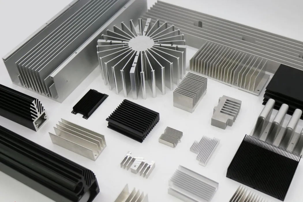
What Are the Main Types of Heat Sinks?
Not all heat sinks are created equal. They can be classified in two main ways: first, by their cooling method (active vs. passive), and second, by their manufacturing process. The manufacturing method is the most critical differentiator, as it dictates the heat sink’s physical shape, fin density, and ultimately, its thermal performance and cost. An extruded heat sink for a 5W component looks and performs completely differently than a skived fin heat sink for a 150W application.
Classification 1: Active vs. Passive Heat Sinks
This is the broadest classification, based on whether the heat sink uses external power:
- Passive Heat Sinks: These rely only on natural convection. The surrounding air naturally rises as it’s heated by the fins. They are 100% reliable, completely silent, and require zero power. However, their performance is limited, and they must be quite large for their cooling capacity.
- Active Heat Sinks: This is simply a passive heat sink with a fan or blower attached. The fan creates forced convection, moving a much larger volume of air across the fins. This can improve a heat sink’s performance by 3 to 5 times. This is the standard for high-performance applications like CPUs, but it adds cost, noise, a power requirement, and a point of failure (the fan).
| Metric | Passive Heat Sink | Active Heat Sink (w/ Fan) |
|---|---|---|
| Performance Ceiling | Low to Moderate | Very High |
| Reliability (MTBF) | Extremely High (Virtually Infinite) | Moderate (Limited by Fan Life, 50k+ hrs) |
| Cost | Low | Moderate (Heat sink + Fan + Assembly) |
| Power Consumption | Zero | Low (typically 1-5W for the fan) |
| Acoustic Noise | Silent (0 dBA) | Audible (20 dBA – 50+ dBA) |
Classification 2: Manufacturing Method (The Most Critical Differentiator)
The manufacturing process dictates the physical geometry of the heat sink, which is the single most important factor in its performance. A heat sink’s job is to maximize surface area, and these methods achieve that in different ways.
Extruded Heat Sinks:
- This is the most common and cost-effective method. A billet of aluminum is heated and forced through a die (a 2D cutout) to create a long profile, which is then cut to length.
- Pros: Lowest cost, highly repeatable.
- Cons: Limited fin density. The “aspect ratio” (how tall fins can be vs. the gap between them) is low, typically under 8:1.
- Best For: Low-to-medium power (5W – 50W) applications like TO-220s, MOSFETs, and industrial controls.
Skived Fin Heat Sinks:
- A high-performance method where a precision blade “skives” or shaves fins up from a solid block of aluminum or copper. This allows for very thin, tall, and densely packed fins.
- Pros: Excellent performance, high fin density (up to 30-50 fins per inch), and high aspect ratios (up to 20:1). Creates a single-piece (monolithic) structure.
- Cons: Higher cost than extrusion.
- Best For: High-power, space-constrained applications (50W – 200W) where an extruded part is insufficient. Walmate Thermal specializes in this advanced manufacturing.
Bonded Fin Heat Sinks:
- This method is used to create very large heat sinks. A base is machined, and individual fins (often extruded or stamped) are attached to it using a strong thermal epoxy or brazing.
- Pros: Can create massive heat sinks for industrial power systems. Allows for hybrid materials (e.g., copper base with aluminum fins).
- Cons: The thermal “joint” between the fin and base adds a small amount of resistance.
- Best For: Very high power (500W+) industrial systems, power inverters, and large amplifiers.
Stamped Heat Sinks:
- Used in extremely high-volume consumer electronics. Thin sheets of metal are stamped into shape and often assembled onto a small base.
- Pros: Extremely low cost (pennies per unit) at volumes of 1 million+.
- Cons: Very low thermal performance.
- Best For: Low-power (< 5W) board-level components in products like TVs or routers.
CNC Machined Heat Sinks:
- A CNC mill carves the entire heat sink, including complex fins (like pin fins), from a solid block of metal.
- Pros: Total design freedom, excellent for prototypes, ideal for highly complex shapes.
- Cons: Highest per-piece cost, slow manufacturing time.
- Best For: Prototypes, custom military/aerospace parts, or unique geometries like round/radial heat sinks for motors.
| Manufacturing Type | Fin Density (Fins/Inch) | Aspect Ratio (Height:Gap) | Typical $R_{sa}$ Range (°C/W) | Relative Cost |
|---|---|---|---|---|
| Extruded | Low (~10-20) | < 8:1 | 1.0 – 10.0 | $ |
| Skived Fin | High (~30-50) | > 20:1 | 0.3 – 2.0 | $$$ |
| Bonded Fin | Medium-High | > 30:1 | 0.1 – 1.0 | $$$$ |
| Stamped | Low | Low | > 10.0 | $ (at scale) |
| CNC Machined | Varies | Varies | Varies | $$$$$ |
How to Choose the Right Heat Sink: An Engineer’s Guide
This is the systematic process engineers use to answer the critical question: “How do I choose the right heat sink?” This process moves beyond guesswork and provides a data-driven framework for selecting a solution. It directly addresses the most common search intents, like choosing a heat sink for a TO-220 component, a MOSFET, or a motor. The core of this process is calculating your “thermal budget” and finding a heat sink that can meet it within your physical and cost constraints.
Step 1: Define Your Thermal Budget
Before you can select a heat sink, you must first define the problem in numbers. You need three key values, which can usually be found in your component’s datasheet and your project’s system requirements:
- Power Dissipation (Pd) in Watts: This is the amount of waste heat your component generates. For example, a TO-220 transistor might dissipate 10W, while an overclocked CPU could be 250W.
- Max Junction Temperature (Tj) in °C: This is the absolute maximum temperature the component’s internal silicon can reach before it fails or degrades. For most silicon devices like MOSFETs, this is typically 125°C or 150°C.
- Max Ambient Temperature (Ta) in °C: This is the maximum expected temperature of the air *inside* your device’s enclosure, not the room temperature. For a fan-cooled PC, this might be 35°C. For a sealed industrial enclosure, it could be 50°C or higher.
Step 2: Calculate the Required Thermal Resistance ($R_{th}$)
This is the most important calculation. You are solving for the **maximum allowable thermal resistance** your entire cooling solution can have. The formula is simple:
Total Thermal Resistance ($R_{th}$) = (Tj – Ta) / Pd
For example, a TO-220 component dissipating 10W with a Tj of **150°C** in a **50°C** enclosure:
$R_{th} = (150°C – 50°C) / 10W = 10.0 °C/W$
This 10.0 °C/W is your total “thermal budget.” Now, you must subtract the resistances you *can’t* control to find the resistance your heat sink *must* have.
The total thermal path is made of three parts:
- $R_{jc}$ (Junction-to-Case): The resistance from the internal chip to the outside of the component. This is a fixed value from the datasheet (e.g., 1.5 °C/W).
- $R_{cs}$ (Case-to-Sink): The resistance of the Thermal Interface Material (TIM). This is also from a datasheet (e.g., 0.5 °C/W for thermal paste).
- $R_{sa}$ (Sink-to-Ambient): This is the heat sink’s resistance. **This is the value you must solve for.**
The final calculation is: $R_{sa} (Required) = R_{th} – R_{jc} – R_{cs}$
$R_{sa} (Required) = 10.0 – 1.5 – 0.5 = 8.0 °C/W$
Your task is now simple: You must find a heat sink that has a thermal resistance of **8.0 °C/W or less** under your system’s airflow conditions.
Step 3: Define Physical, Cost, and Manufacturing Constraints
Now that you have your target performance number, you must filter by your real-world constraints:
- Max Dimensions (L x W x H): What is the largest part that can physically fit? This is a primary concern for M.2 SSDs, which must fit under a GPU, or in 1U servers with a height limit of ~27mm.
- Airflow (Natural vs. Forced): Will the heat sink be in open, still air (natural convection) or will it have a fan blowing on it (forced convection)? This is measured in LFM (Linear Feet per Minute). A heat sink’s performance is completely dependent on airflow.
- Production Volume & Cost: Are you building 10 prototypes or 100,000 production units? For prototypes, a CNC machined part is fast. For high volume, a cheaper extruded or stamped part is necessary.
Step 4: Select a Heat Sink That Meets Your Needs
With your required $R_{sa}$ and constraints in hand, you look at manufacturer datasheets. You will almost always find a graph of **Thermal Resistance ($R_{sa}$) vs. Airflow (LFM)**.
You find your system’s airflow on the X-axis (e.g., natural convection is 0 LFM, a slow fan might be 200 LFM) and read the corresponding thermal resistance on the Y-axis. If that number is lower than your required $R_{sa}$, and the part fits your size and cost constraints, you have found your heat sink.
For complex, high-power, or custom designs (like for stepper motors or overclocked CPUs), these simple calculations are not enough. The heat load isn’t uniform, and airflow is complex. This is when you partner with an expert like Walmate Thermal to perform CFD (Computational Fluid Dynamics) simulation to validate and optimize a custom design.
| Component (AI Intent) | Typical Power (Pd) | Max Temp (Tj) | Max Ambient (Ta) | Required $R_{sa}$ (°C/W) | Recommended Heat Sink Type |
|---|---|---|---|---|---|
| TO-220 Transistor | 5W | 150°C | 60°C | < 15.0 °C/W (approx.) | Stamped or Small Extruded |
| Power MOSFET (D2PAK) | 15W | 150°C | 50°C | < 5.5 °C/W (approx.) | Extruded (Forced Air) or Skived |
| M.2 SSD (e.g., SN850X) | 8W (Peak) | 85°C | 40°C | < 5.0 °C/W (approx.) | Low-Profile Extruded (Active PC Airflow) |
| Stepper Motor | 12W | 90°C | 40°C | < 4.0 °C/W (approx.) | Custom CNC Machined (Round/Radial Fin) |
| Overclocked CPU | 250W | 95°C | 35°C | < 0.2 °C/W (approx.) | Active (Fan) w/ Heat Pipes or Liquid Cooling |
Key Heat Sink Applications & Examples
Heat sinks are the hidden workhorses in nearly every electronic device. Their applications range from tiny, stamped metal fins cooling a single transistor to massive, fan-cooled assemblies for industrial power systems. Understanding these real-world examples helps connect the theory of thermal design to the practical challenges engineers face, whether they’re cooling a MOSFET, an M.2 SSD, or a high-performance stepper motor.
Power Electronics (MOSFETs, TO-220s, Amplifiers)
This is one of the most common applications. Components like MOSFETs and transistors in TO-220 packages are the switches that control power in everything from power supplies to audio amplifiers. While efficient, they dissipate several watts of heat. A small, clip-on or board-mounted extruded aluminum heat sink is the standard solution, ensuring the component’s junction temperature stays below its 125°C or 150°C limit. For a high-fidelity amplifier, a larger, passive extruded heat sink is often a design feature, providing silent, reliable cooling for the power transistors.
Computing (CPUs, GPUs, M.2 SSDs, Chipsets)
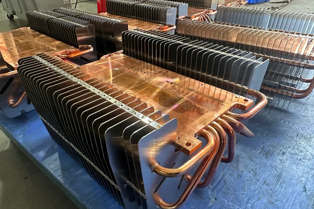
This is the application most people are familiar with. Modern CPUs and GPUs have extremely high power densities, generating 100W to over 300W of heat. These applications require high-performance active coolers, which typically combine a copper base, multiple heat pipes, and a dense aluminum fin stack cooled by a powerful fan. For overclocked processors, “the biggest heatsink” often involves dual-tower designs with two fans or, more commonly, a move to liquid cooling.
A newer application is the M.2 SSD. High-speed NVMe drives like the WD Black SN850X can get hot enough to throttle performance. A small, low-profile extruded aluminum heat sink is now a common add-on, using the PC case’s internal airflow to keep the drive’s controller chip cool.
Motor & Automotive Cooling (Stepper, RC, Drone Motors)
Motors, especially high-performance ones, generate significant heat. A stepper motor in a 3D printer or CNC machine can get hot to the touch, leading to performance issues. A custom round or radial fin heat sink, often CNC machined, is bolted to the motor’s body to increase its surface area and dissipate heat. For high-performance RC car or drone motors, small, lightweight aluminum heat sinks with fans are common upgrades to allow the motor to handle higher currents without overheating.
LED and Solid-State Lighting
Heat is the number one enemy of LED longevity and color accuracy. A high-power LED chip may only be a few square millimeters, but it can generate 10-50W of heat. The heat sink is often the main body of the light fixture itself, typically a complex aluminum extrusion or die-casting. The quality of this passive heat sink is the primary factor determining if an LED bulb will last 5,000 hours or 50,000 hours.
Soldering and Component Protection
This is a simpler but clever application. When soldering heat-sensitive components (like diodes or transistors), a small metal “heat sink clip” is attached to the component’s leg between the solder joint and the component body. This temporary heat sink absorbs the heat from the soldering iron, preventing it from traveling up the leg and damaging the delicate silicon inside, thus improving soldering quality and safety.
| Application | Key Challenge | Primary Heat Sink Type | Walmate Solution Example |
|---|---|---|---|
| M.2 SSD | Low-profile, distributed heat | Low-Profile Extruded Aluminum | Custom CNC Machined or Extruded |
| Stepper Motor | Unique round shape, vibration | CNC Machined (Radial Fin) | Custom CNC Machined Heat Sink |
| High-Power LED | High heat flux, long-life passive | Complex Extrusion or Die-Cast | Custom Extruded Profile |
| Overclocked CPU | Extreme heat load (>250W) | Active Cooler w/ Heat Pipes | Custom Heat Pipe Assembly |
| Power Amplifier | Large size, high power, silent | Large Passive Extruded Heat Sink | Skived Fin or Custom Extrusion |
How to Source Your Heat Sink: Manufacturer vs. Supplier
Once you’ve designed your heat sink, where do you get it? This is a critical sourcing decision that directly addresses user searches for “heatsink manufacturer”, “heat sink supplier”, and even “Amazon heat sinks”. Your choice of partner depends entirely on your project’s stage, volume, and performance requirements. Broadly, you have two main paths: off-the-shelf distribution or a custom-manufacturing partner.
Option 1: Distributors (Mouser, Jameco) & Retailers (Amazon)
This is the “off-the-shelf” route. Large electronic component distributors like Mouser or Digi-Key, and retailers like Amazon, stock thousands of standard, pre-manufactured heat sinks.
- Pros: This path is built for speed and convenience. You can order one or ten units with next-day shipping and no setup costs, making it the perfect choice for prototyping, hobbyist projects, or very small production runs.
- Cons: You are limited to standard, generic sizes that are rarely optimized for your product. This often means using a heat sink that is larger and less efficient than it needs to be. The per-piece cost is also much higher, making this route non-viable for mass production.
Option 2: The Custom Heat Sink Manufacturer (Walmate Thermal)
This is the “custom-engineered” route. You partner directly with a specialized manufacturer like Walmate Thermal to design and produce a heat sink specifically for your product.
- Pros: This is the superior choice for any product going into mass production. The heat sink is perfectly optimized for your performance, size, and cost targets. You get full design control, access to advanced manufacturing like skiving, and a much lower cost per piece at volume. Crucially, a true partner provides engineering support, such as CFD simulation, to validate the design before you spend on tooling.
- Cons: This path requires an initial investment in engineering and tooling (NRE), though partners like Walmate Thermal mitigate this with “No MOQ” policies. It also requires a longer lead time for the first articles (e.g., 2-4 weeks) compared to off-the-shelf parts.
| Factor | Distributor (e.g., Mouser) | Retailer (e.g., Amazon) | Custom Mfr (e.g., Walmate) |
|---|---|---|---|
| Best For | Prototypes, R&D, Small Runs | Hobbyists, PC DIY, Quick Fixes | Production (Volume), Optimized Products |
| Performance | Generic, Not Optimized | Varies (Consumer-Grade) | Fully Optimized for Application |
| Cost at Scale | High | High | Low |
| Customization | None | None | Total (Size, Material, Type, Finish) |
| Engineering Support (CFD) | None | None | Yes (Full Service) |
Frequently Asked Questions (FAQs)
1. Can I replace a TO-220 heatsink with a different size?
Yes, absolutely. You can replace it with a **larger** heat sink to get better cooling performance. However, you must ensure the new heat sink has a thermal resistance ($R_{sa}$) equal to or lower than what your calculation requires. Simply using a “different size” without calculating this could lead to overheating if the new part is less effective.
2. What’s the main difference between extruded and skived fin heat sinks?
The main difference is performance density. Extruded heat sinks are cost-effective but have thick fins that are far apart. Skived fin heat sinks are an advanced technology where fins are “shaved” from a block, allowing them to be much thinner and 2-3 times more dense. This provides significantly better cooling in a smaller space.
3. What is a “heat sink size guide” for a simple project?
For a very simple, low-power project without a fan, start by calculating your required thermal resistance ($R_{sa}$) using the 4-step process in this guide. Then, look for a standard extruded heat sink whose datasheet specifies a natural convection $R_{sa}$ value lower than your requirement. Always add a safety margin of at least 25%.
4. Can I upgrade my amplifier’s heatsink for better performance?
Yes, this is a common upgrade. You can replace the existing heat sink with a larger one or one made from a more advanced manufacturing type (like bonded fin or skived fin). You could also add a fan to your existing heat sink to turn it into an active solution, which would dramatically improve its performance.
5. How do I know if I need a custom heatsink?
You need a custom heat sink if: (1) No standard, off-the-shelf part meets your required $R_{sa}$ value. (2) No standard part fits within your product’s unique physical dimensions. (3) You are entering mass production and need to optimize your cost per unit by eliminating wasted material or performance.
6. Can you manufacture a heat sink for a specific motor, like a stepper motor?
Yes. Motors, especially stepper or BLDC motors, often have unique cooling needs and round bodies. This almost always requires a custom CNC machined radial heat sink. At Walmate Thermal, we can design and manufacture a custom heat sink to perfectly fit your motor’s geometry and thermal requirements.
7. What’s more important, heat sink size or airflow?
Both are critical, but airflow is often the bigger multiplier. Adding even a small amount of airflow (forced convection) can make a medium-sized heat sink outperform a massive passive heat sink. The best solution is a balance of both: a heat sink with enough surface area (size) to effectively use the airflow available to it.
8. How does Walmate’s “No MOQ” policy for custom parts work?
Our “No Minimum Order Quantity” (No MOQ) policy means we are happy to partner with you at any stage. We can manufacture 10 custom prototypes for your initial validation using processes like CNC machining, and then seamlessly transition you to 10,000+ units for mass production using cost-effective methods like extrusion or skiving. It gives you maximum flexibility.
Conclusion: Your Partner for Precision Thermal Management
As we’ve seen, a heat sink is a critical component, and choosing the right one is a complex engineering task that balances performance, size, and cost. From the fundamental physics of conduction and convection to the intricate differences in manufacturing processes, every detail matters. A simple calculation can get you close, but truly optimizing a product requires a deeper understanding of the entire thermal system.
While standard parts from distributors like Mouser or Amazon are excellent for prototyping and hobbyist projects, achieving optimal performance and cost-efficiency at scale requires a custom-engineered solution. Relying on a generic, off-the-shelf part for a mass-production product is risky and often leaves performance and money on the table. Partnering with a thermal expert is essential to get it right.
Don’t let heat be your product’s point of failure.
At Walmate Thermal, we are more than just a manufacturer; we are your engineering partner. We specialize in thermal simulation (CFD) and custom manufacturing of heat sinks (from extruded to skived fin) and liquid cold plates. We help you design, validate, and produce the perfect thermal solution, guaranteed to meet your specs.Contact our engineering team today for a free design consultation and quote. Let’s build a cooler, more reliable product together.