Designing an effective cooling system starts with one challenge—understanding how heat flows through materials and how to control it. For engineering students and hobbyists, mastering the thermal resistance equation is the key to building efficient, compact, and reliable heat management solutions.
This guide walks through the thermal resistance equation, how to calculate the required °C/W rating, and how to use these results to design heatsinks with confidence. By the end, you’ll know how to align your calculations with real-world performance and create designs that stay cool under pressure.
Stop Guessing: Design Your Heatsink With Math
Mathematical design of heatsinks eliminates guesswork by using thermal resistance equations and heat transfer principles to calculate required fin geometry, material properties, and airflow rates needed to meet specific cooling performance targets. This approach allows optimization of thermal performance, size, and cost before building physical prototypes.
Instead of relying on repeated physical testing, engineers can now evaluate heatsink performance through precise mathematical models. Using the thermal resistance equation and computational tools, design teams can quickly find the best balance between size, airflow, and material. This process helps achieve efficient cooling and ensures that every design aligns with performance goals before production.
Key Design Parameters and Typical Values (Table)
These are the core parameters used in early heatsink design calculations. The values help define how materials and geometry influence cooling capacity and cost.
| ⚙️ Parameter | 📊 Typical Value |
|---|---|
| Aluminum Thermal Conductivity | 210 W·m⁻¹·K⁻¹ |
| Aluminum Density | 2,710 kg·m³ |
| Aluminum Specific Heat | 900 J·kg⁻¹·K⁻¹ |
| Free Convection Coefficient | 9.0 W·m⁻²·K⁻¹ |
| Typical Fin Height | 17.5 mm |
| Typical Fin Thickness | 2 mm |
| Standard Fin Count | 10 fins |
| Simulation Accuracy | ✅ Reasonably accurate in initial design phase |
Mathematical Foundations and Computational Approach
The thermal resistance equation links all major components of heat transfer — from the device’s junction to the surrounding air. By breaking this path into junction-to-case and case-to-ambient resistances, designers can identify the maximum allowable temperature rise and required fin geometry.
Parametric modeling connects geometry, material conductivity, and environmental factors into a single design equation. This technique makes it easy to adjust design variables such as fin spacing, thickness, and base area. Each variation updates the predicted performance in real time, guiding choices early in the design phase.
In our experience, tools like finite element analysis (FEA) and state-space simulation models are widely used in the industry. They recreate complex thermal dynamics of 3D models and use accurate meshing to predict hot spots, airflow effects, and transient temperature changes. These models reduce costly prototype iterations.
Optimization Techniques and Practical Validation
Once the mathematical model is defined, optimization software can fine-tune each design. The system adjusts fin shape, topology, and spacing automatically until a target thermal performance is achieved. This intelligent process minimizes manual trial adjustments.
- 🚀 Shape, topology, and parametric optimizations refine fin geometry for desired cooling.
- 💡 Lookup tables of convection coefficients help reflect actual airflow rates and mass flow conditions.
- ✅ CFD (Computational Fluid Dynamics) methods, such as porous media modeling, provide accurate pressure drop and heat transfer data.
- ⚠️ Practical trade-offs exist between increasing fin surface area and keeping mass and air resistance under control.
To verify simulation accuracy, engineers often compare results against empirical test data under similar operating conditions. This step validates that computed results can reliably guide production designs and ensures cost-effective performance.
Common Misconceptions and Design Insights
It is common to assume that bigger means better when it comes to heatsinks, but that’s rarely true. Larger fins increase airflow resistance and can lead to a smaller net cooling benefit.
- ⚠️ Oversized fins can cause excessive pressure drop, reducing effective air velocity.
- 💡 Optimization focuses on balancing fin area with manageable flow resistance for best results.
- 🚀 Mathematical modeling allows rapid testing of design alternatives before committing to prototypes.
- ✅ Advanced computations reveal how subtle changes in geometry or material impact overall performance.
By relying on data, not assumptions, designers achieve superior cooling with minimal material use. This mathematical approach reflects the same philosophy used by professional engineering teams at Walmate Thermal to deliver reliable, efficient heat dissipation solutions across power electronics, EVs, and industrial systems.
The Master Equation: R=ΔT/Q
The master equation for thermal resistance is R = ΔT / Q, where R denotes thermal resistance in kelvin or celsius per watt, ΔT is the temperature difference across a material, and Q is the heat transfer rate in watts. The equation quantifies how materials resist heat flow for a given temperature gradient and heat flux.
This section explains how the fundamental thermal resistance equation applies to real-world heat management practices. Engineers often use it to evaluate materials, compare performance, and estimate heat dissipation capacity across various cooling systems.
Understanding the Thermal Resistance Equation
Thermal resistance tells how much a material resists heat flow. It’s expressed as R = ΔT / Q, where each variable has a measurable physical meaning and unit.
- 💡 Thermal resistance (R): Measured in K/W or °C/W.
- 💡 Temperature difference (ΔT): Measured in K or °C, representing the gradient across the medium.
- 💡 Heat transfer rate (Q): Measured in W, representing the heat flow through the material.
The formula shows that for a given heat flow, a higher temperature difference means higher thermal resistance. In our experience at Walmate Thermal, this principle guides the design of efficient heat sinks and liquid cooling systems to minimize resistance and improve performance.
Alternative Formulation Using Fourier’s Law
Fourier’s Law allows another way to express thermal resistance using the geometry and conductive properties of materials. The relationship is given by R = Δx / (k × A).
- 📏 Δx: Material thickness in meters (m).
- 🔬 k: Thermal conductivity in W/(m·K)—a measure of how well a material conducts heat.
- 📐 A: Cross-sectional area perpendicular to the heat flow in m².
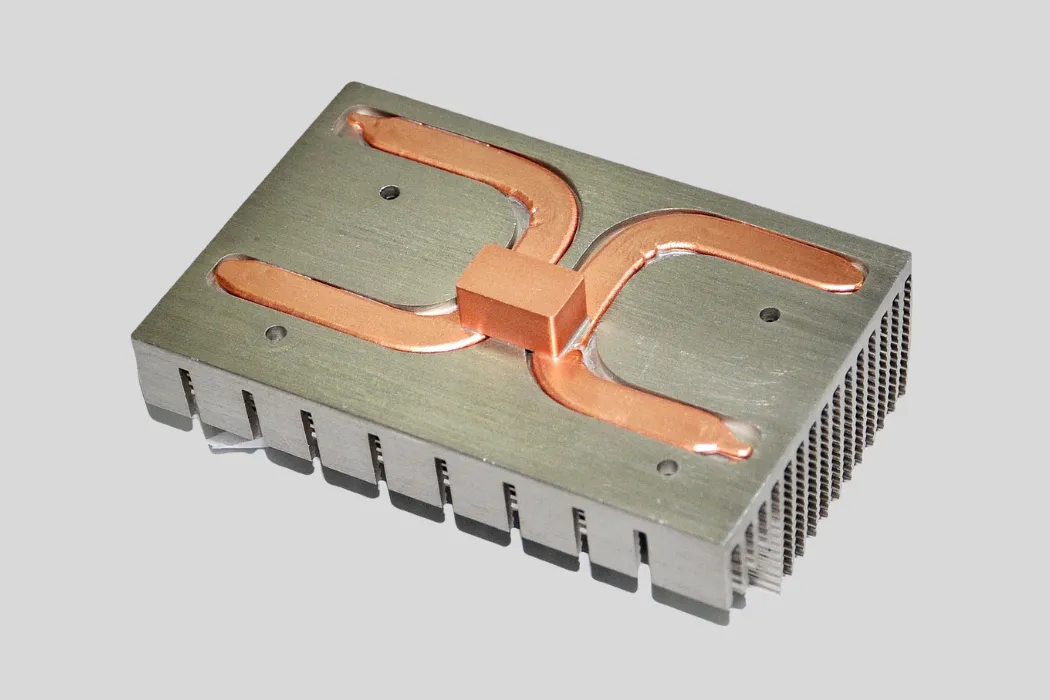
For example, a copper plate of 2 mm thickness (0.002 m), thermal conductivity of 400 W/m·K, and area 0.01 m² would have a resistance of approximately 0.0005 K/W. Such low resistance makes copper an excellent conductor in heat sinks and cold plates used by Walmate Thermal in industrial and automotive cooling applications.
Deeper Insights and Common Misconceptions
Thermal resistance is often mistaken for thermal conductivity. Yet conductivity describes a material property, while resistance includes geometry, meaning two materials with identical conductivity can have different resistances based on thickness or surface area.
- ⚠️ Interfaces between components can dominate total resistance, often more than the bulk material itself.
- ⚙️ In multilayer assemblies, resistances add in series for accurate system-level modeling.
- 📏 Always apply consistent units (K/W or °C/W) and use the equation for steady-state conditions.
- 🚀 To reduce resistance: increase contact area, reduce thickness, or select materials with higher k values.
At Walmate Thermal, our engineers pay special attention to contact interfaces and assembly alignment because even small imperfections can drastically increase system resistance. By optimizing geometry and material matching, we ensure that our heat sinks, liquid cold plates, and TEC modules achieve efficient and reliable thermal performance across power electronics, EVs, and new energy systems.
Step 1: Determine Your Heat Load (Watts)
To determine your heat load in watts, calculate the total heat generated by all components in your system, including electronics, motors, and any other heat sources, using the formula: Heat Load (W) = Power Input (W) × Duty Cycle × Number of Units.
Estimating total heat load is the first step in designing an efficient thermal management system. It helps you size your cooling hardware accurately and ensure components such as heat sinks or liquid cold plates from Walmate Thermal perform at their best.
What Is Heat Load?
Heat load is the total amount of thermal energy released by all devices and structural elements in a system, measured in watts (W). It comes from a mix of internal and external heat sources and directly affects temperature stability.
In our experience, it includes heat from electronic boards, power modules, motors, lighting, occupants, and environmental factors like sunlight or wall conduction. An accurate assessment of heat load allows engineers to select the right cooling approach, minimizing overheating and energy waste.
Common Heat Load Sources and Typical Values
Different components and environments generate heat at varying rates. The table below provides a quick reference for typical values often used when modeling heat loads for labs, workshops, or test benches.
| Source | Typical Heat Load |
|---|---|
| 💡 Desktop computer | 100–300 W |
| 🖥️ Server rack | 500–2,000 W |
| ⚙️ Small motor (1/2 HP) | 373 W |
| 💡 LED lighting (per 100W fixture) | 80–100 W |
| 🔥 Small industrial oven | 1,000–5,000 W |
| 👥 People (per person) | 100 W sensible + 70 W latent |
| ☀️ Windows (direct sun, per m²) | 100–200 W |
| 🏠 Exterior wall (uninsulated) | 50–100 W per m² |
| 🏠 Exterior wall (insulated) | 10–30 W per m² |
Calculating Heat Load: Key Factors and Formulas
To calculate your total heat output, start with the formula Heat Load (W) = Power Input (W) × Duty Cycle × Number of Units. The duty cycle represents how often a device operates. A device that runs continuously uses a factor of 1.0, while one that cycles on and off may range between 0.5–0.8.
Include all major heat contributors: electronic devices, lighting, motors, building elements, and even people. Don’t forget thermal transfer through structural components. The thermal resistance equation, written as Q = (T_in − T_out) / R, helps estimate heat flow when temperature difference and thermal resistance are known.
In our projects with Walmate Thermal’s customers, incorporating accurate resistance values has led to more precise cooling plate and heat sink designs that ensure reliable temperature control.
Common Challenges and Best Practices
When estimating heat load, several mistakes can distort results. To avoid them, apply these reliable practices used by our engineering teams.
- ⚠️ Avoid underestimating internal heat gains from occupants and small appliances.
- ⚠️ Include latent heat effects where moisture or humidity is involved.
- 💡 Consider peak operating loads and allow room for future upgrades.
- ✅ Use conservative margins to prevent undersized cooling systems.
- 🚀 Regularly validate calculations with measured data to refine models over time.
Accurate heat load data ensures Walmate Thermal’s heat sinks, liquid cooling plates, and TEC modules perform effectively across industries from electric vehicles to high-power inverters. Proper calculation is the foundation of any successful thermal design.
Optimize Your Thermal Management with Industry-Leading Expertise
Partner with Walmate Thermal to leverage nearly 20 years of innovative R&D and manufacturing excellence, ensuring your products perform at peak efficiency. Our custom-designed, system-level cooling solutions empower industries from EVs to AI with precise, reliable thermal control.
Step 2: Find Your Max Junction Temp (Tjmax)
The Max Junction Temperature (Tjmax) is the highest temperature the semiconductor junction can reach without risking permanent damage or failure, and it is always specified by the manufacturer in the device’s datasheet.
Understanding Tjmax is a key step when using the thermal resistance equation to size your heat sink or select a cooling method. For engineers, this value defines the thermal limit that dictates how much heat must be managed through conduction, convection, or radiation to maintain performance stability.
Definition and Importance of Tjmax
Tjmax refers to the maximum temperature that the semiconductor junction can safely tolerate before irreversible damage occurs. Devices that operate above this limit may experience thermal runaway or fail completely.
Manufacturers define Tjmax as a fixed, non-negotiable number provided in datasheets. It is not the recommended operating temperature but the absolute ceiling value. In our experience at Walmate Thermal, maintaining junction temperatures well below this limit increases component reliability and extends service life.
Designers must always consider this parameter early in thermal design because it directly influences required heat sink capacity and airflow considerations for electronic devices and power modules.
Typical Tjmax Values for Different Device Types
Different semiconductor technologies have varying Tjmax limits, depending on material and construction characteristics. The table below highlights common ranges used in engineering practice.
| Device Type | Typical Tjmax | Example | Notes |
| 💡 Silicon-based Devices | 125°C – 175°C | Standard MOSFETs, BJTs | ✅ Common in most power electronics |
| 💡 SiC & GaN (Wide Bandgap) | Over 200°C | SiC MOSFETs, GaN HEMTs | 🚀 Enables higher power density and compact systems |
| 💡 Example Device | 185°C | Renesas IGBT AE5 | ⚠️ Single, non-negotiable limit in datasheet |
From silicon to wide-bandgap materials, higher Tjmax values allow for more compact designs but require equally advanced cooling technologies. Systems operating near these upper limits must use reliable heat sink assemblies, optimized airflow, or even liquid cooling for safe operation.
Implications of Tjmax for Thermal Management Design
Tjmax is not only a number—it’s a design constraint that defines how much temperature rise can occur between the junction and ambient environment. Designers use it when applying the thermal resistance equation (RθJA = (Tjmax – Ta) / P) to determine the maximum allowable thermal resistance from junction to air.
- ⚠️ Operating near Tjmax shortens lifespan and may activate thermal protection circuits.
- 💡 Tjmax helps calculate maximum power dissipation and determines cooling system requirements.
- ✅ Effective thermal management involves proper use of heat sinks, fans, or liquid cold plates to keep junction temperatures safely below Tjmax.
- 🚀 Derating power devices based on datasheet Tjmax improves long-term reliability.
In practice, systems are designed with safety margins to ensure steady performance even under varying ambient conditions. At Walmate Thermal, our engineers often combine CFD analysis with empirical testing to validate that junction temperatures remain well below rated Tjmax, even under sustained high-load conditions. This preventive approach minimizes thermal degradation and enhances product durability in industrial and automotive environments.
Step 3: Measure Ambient Temp (Tamb)
To measure ambient temperature (Tamb) accurately for thermal resistance calculations, use a calibrated sensor such as a thermistor, RTD, or thermocouple placed away from heat sources and airflow disturbances, ensuring the reading reflects the true environmental temperature surrounding the device.
Ambient temperature plays a vital role in thermal resistance analysis because it sets the reference point for evaluating heat buildup in any system. In our experience with Walmate Thermal’s projects across power electronics and EV cooling, even a small deviation of a few degrees can significantly impact simulation results and component reliability.
Common Ambient Temperature Sensors
Choosing the right sensor is key to reliable measurements in the thermal resistance equation. Each sensor type offers different accuracy, range, and response time depending on the application environment.
| Sensor Type | Temperature Range | Accuracy | Notes |
|---|---|---|---|
| Thermocouple | −200°C to 1800°C | ±1–2°C | ✅ Wide range, ⚠️ needs reference compensation |
| RTD (PT100/PT1000) | −200°C to 850°C | ±0.1–0.5°C | ✅ High accuracy, ⚠️ sensitive to lead resistance |
| Thermistor | −100°C to 300°C | ±0.2–2°C | ✅ Small and responsive, ⚠️ nonlinear at extremes |
| IC Sensor | −55°C to 150°C | ±0.5°C | ✅ Digital output, ⚠️ limited range |
Sensor Placement Guidelines
Correct sensor placement ensures readings represent true ambient conditions rather than localized heat or cooling zones. Small errors in position can distort calculations in high-precision designs.
- 💡 Keep sensors at least 5–10 cm away from heat sources like power chips or transformers.
- ⚠️ Avoid spots under direct sunlight or near cooling fan drafts to prevent artificial temperature shifts.
- ✅ Place the sensor where it captures the average environmental air temperature surrounding the device under test.
In industrial setups that Walmate Thermal engineers manage, this method ensures consistent reference readings even in high-density enclosures or liquid-cooled environments.
Calibration and Measurement Error Considerations
Even high-quality sensors require periodic calibration to maintain accuracy. Environmental exposure, electrical interference, and material aging can slowly shift readings over time.
- ✅ Calibrate every 6–12 months to compensate for drift and maintain precision.
- ⚠️ Reduce self-heating errors in RTDs by limiting current, which can add up to 0.5°C of error.
- 💡 Use a 4-wire configuration to remove lead resistance effects in RTDs.
- ⚠️ For IR-based sensors, shield them from reflected radiation that may misrepresent real ambient values.
Importance of Accurate Ambient Temperature Measurement
Ambient temperature provides the baseline in every thermal resistance equation, determining how effectively a heatsink or cooling solution dissipates energy. An incorrect measurement shifts the ΔT (temperature rise) calculation and results in misleading performance data.
- ✅ Proper measurement ensures valid comparison between test samples and real-world conditions.
- ⚠️ Misplaced sensors or uncalibrated devices can lead to deviations of several degrees, misleading engineers during thermal modeling.
- 💡 Using high-accuracy RTDs or calibrated thermistors minimizes drift and supports repeatable tests.
- ✅ Implement shielding and isolation to mitigate radiative and convective interference for consistent and reliable readings.
In our experience, these ambient measurements underpin Walmate Thermal’s entire cooling solution design process, from LED lighting modules to EV battery systems, ensuring trustworthy data for optimized thermal management and material performance.
Step 4: Calculate the Required ∘C/W Rating
Calculate the required °C/W thermal resistance using the formula: Rth = (Tj,max – Ta)/Pmax, where Tj,max is the maximum junction temperature, Ta is the ambient temperature, and Pmax is the maximum power dissipation.
The required thermal resistance rating determines how efficiently a component can dissipate heat to operate safely. Understanding this helps ensure your design remains within temperature limits and maintains reliability under load.
Thermal Resistance Calculation Formula
The thermal resistance equation provides a way to calculate the cooling performance needed for an electronic device. The formula is:
Rth = (Tj,max – Ta) / Pmax
Here’s what each term represents:
- 💡 Tj,max — the maximum safe junction temperature (e.g., 125°C for a silicon transistor).
- 💡 Ta — the ambient temperature around the device, typically about 21°C for commercial conditions.
- 💡 Pmax — the maximum power dissipation in watts.
Example calculation: For a device dissipating 2W, the required thermal resistance rating is (125 – 21)/2 = 52 °C/W. This value helps determine the needed heatsink or cooling system performance.
Key Components Affecting Thermal Resistance
In practice, several layers contribute to total thermal resistance from the chip junction to the environment. Each layer adds to the total °C/W value in the heat dissipation path.
- ⚙️ Junction-to-case resistance — inherent to the semiconductor package.
- ⚙️ Case-to-heatsink resistance — depends on how well the heatsink interfaces with the device.
- ⚙️ Heatsink-to-ambient resistance — determined by heatsink design and airflow conditions.
Heatsink performance varies by type: a typical TO-220 package heatsink has about 4 °C/W resistance. Thermal interface materials (TIMs) also matter—a surface with compound can achieve around 0.25 °C/W, while one without compound may rise to 1 °C/W. These differences can greatly affect cooling efficiency.
Practical Considerations and Best Practices
Even a precise calculation can fall short if practical details are overlooked. Always use realistic and conservative values when evaluating the environment and device performance.
- ⚠️ Use safety margins by assuming higher ambient temperatures and maximum power loads.
- ⚠️ Ensure every segment of the thermal path is accounted for—missing any resistance factor may cause overheating or failure.
- 💡 Apply thermal compounds evenly to minimize resistance between surfaces and improve contact performance.
- ✅ Select heatsinks so the total combined thermal resistance remains equal to or below the required 52 °C/W threshold for safe operation.
In our experience at Walmate Thermal, properly analyzing each layer of the heat path can prevent costly design errors and extend component life. Our engineering teams apply these same principles when designing custom thermal assemblies across automotive, industrial, and energy sectors.
Reading Datasheets: How to Match Your Calculation to a Product
To accurately match your thermal resistance calculations to a product, you must extract key parameters—such as junction-to-ambient thermal resistance (RθJA), maximum power dissipation, and recommended operating conditions—directly from the product’s datasheet and ensure your calculated requirements do not exceed these specified limits.
When applying the thermal resistance equation to a real component, understanding how datasheet parameters translate into thermal performance is essential. By aligning your calculations with manufacturer specifications, you can prevent overheating and ensure long-term reliability of the device.
Key Datasheet Parameters to Extract
Every datasheet provides technical data that dictates safe and efficient operation. In our experience, thermal engineers focus on these major parameters when calculating or verifying design performance.
- 💡 Thermal Resistance (RθJA): Typically ranges from 10°C/W for high‑performance packages to around 150°C/W for small surface‑mount devices (SMDs).
- 💡 Maximum Power Dissipation: Specified in watts, often 0.5W, 1.0W, or 2.5W depending on the cooling conditions and package type.
- 💡 Absolute Maximum Junction Temperature (Tj max): Normally rated at 125°C, 150°C, or 175°C for different semiconductor families.
- 💡 Recommended Operating Ambient Temperature: Commonly between -40°C and +85°C or up to +125°C for industrial components.
- 💡 Voltage and Current Ratings: Essential for evaluating whether operating conditions fit the part’s electrical limits.
- 💡 Mechanical Dimensions: Ensure package and heat sink compatibility before prototyping.
- 💡 Typical Application Circuit: Provides design context and hints at effective cooling approaches.
- 💡 Performance Graphs: Show how temperature changes with power or airflow, helping you visualize thermal margin.
Extracting these values lets you correlate the RθJA from the datasheet directly to your heat transfer model. This step prevents mismatches between theoretical estimates and physical hardware performance.
Common Misconceptions and Critical Considerations
Engineers frequently misinterpret datasheet figures, especially regarding thermal resistance. Small details like board layout or testing environment can cause large deviations from published numbers.
- ⚠️ Don’t assume all device packages share the same RθJA; even a different PCB copper area can shift thermal resistance by dozens of °C/W.
- ⚠️ Always consult the Absolute Maximum Ratings section. Exceeding it—even briefly—can irreversibly damage the device.
- ⚠️ Typical values are recorded under ideal conditions, yet real‑world airflow and enclosure constraints lower cooling efficiency.
- 💡 Cross‑verify your calculated maximum power dissipation against datasheet limits and use suggested application circuits for better thermal paths.
- 🚀 Keep track of manufacturer errata or revision notes to avoid outdated specifications during product verification.
Matching the thermal resistance equation to actual datasheet limits ensures a stable design. For complex thermal layouts, engineering teams like Walmate Thermal’s often simulate component cooling performance to confirm that calculated results and physical implementation stay fully aligned.
Garage Guru Example: Designing a 10W LED Cooler
Designing a 10W LED cooler requires understanding the thermal resistance equation and choosing suitable components like heat sinks and fans. It’s essential to manage power dissipation, maintain temperature for optimal LED lifespan, and ensure proper airflow for reliable heat removal.
Cooling a 10W LED is a precise engineering process that balances thermal design, component selection, and physical constraints. In our experience at Walmate Thermal, understanding heat transfer fundamentals and applying efficient design practices builds the foundation for reliable LED performance.
Understanding Thermal Resistance in LED Cooling
Thermal resistance defines how effectively heat moves through materials and systems, expressed in °C/W. It helps quantify how much temperature rise occurs per watt of heat generated.
- 💡 For a 10W LED, the total thermal resistance from junction to ambient must be low enough to keep junction temperature within manufacturer limits.
- ⚙️ The fundamental equation is: Tjunction = Tambient + (Power × Thermal Resistance).
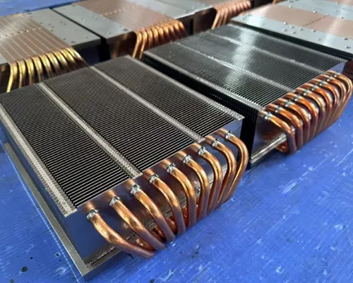
- 🚀 Reducing thermal resistance involves improving heat sink design, applying high-quality thermal interface materials, and optimizing airflow with efficient fan placement.
At Walmate Thermal, we use simulation-based analysis to model these conditions before prototyping, ensuring each design achieves predictable temperature control.
Selecting Components for a 10W LED Cooling Solution
Effective cooling requires a thoughtful combination of materials and components that can handle real-world operating temperatures. Each component contributes to the overall thermal resistance path.
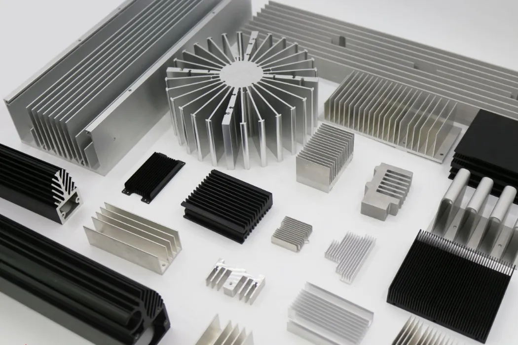
- 🥇 Use heat sinks made with high thermal conductivity materials such as aluminum or copper for efficient heat transfer.
- 🌬️ Add forced convection through small fans to increase airflow and lower surface temperature.
- 🧩 Apply quality thermal interface materials to minimize resistance between the LED and heat sink surfaces.
- ⚠️ Always check mechanical size, mounting type, and cost to ensure these components integrate well with the LED assembly.
Walmate’s product line includes heat sinks, fans, and thermal interface materials that can be customized for compact lighting systems or high-power industrial lamps.
Design Process and Best Practices
The process of designing a thermal management solution for a 10W LED typically follows several key steps to ensure performance and reliability.
- 🧠 Gather LED specifications, including power dissipation rate and maximum operating temperature.
- 📊 Calculate target thermal resistance to ensure proper heat removal from junction to ambient.
- ⚙️ Choose properly rated heat sinks, fans, and thermal interfaces to meet design targets.
- 💡 Simulate airflow and surface temperature using thermal analysis software or CFD tools.
- 🔧 Build prototypes and test them under operating conditions to confirm stability and safety.
At Walmate Thermal, we often apply visualization tools and experimental validation through our R&D centers to fine-tune each prototype before mass production.
Challenges and Critical Considerations
Even when the design follows theoretical models, several practical challenges can influence cooling performance and LED reliability.
- ⚠️ Inadequate cooling may raise LED junction temperature, accelerating degradation and reducing lifespan.
- 💰 Balancing performance, cost, and physical constraints (size, airflow availability) is an ongoing challenge.
- 🌡️ External factors like ambient temperature and enclosure design heavily impact real-world thermal results.
- 🔩 Thermal management systems must maintain both mechanical stability and integration with product aesthetics.
Because Walmate designs solutions across industries—from LEDs to power electronics and EV batteries—the same thermal design principles are applied: control temperature, protect components, and prolong system lifetime.
FAQs: About Thermal Calculations
How do I calculate required heatsink size?
To estimate the proper heatsink size, begin with the device’s typical power dissipation (in W), then decide the maximum operating temperature based on component limits. The basic relationship uses the thermal resistance equation:
Rtotal = (Tmax − Tambient)/P, where P is power in watts. Subtract known resistances such as junction-to-case and case-to-sink to find the required heatsink thermal resistance (°C/W).
Once you find that value, choose a heatsink model or design that achieves that target under given airflow conditions. Walmate Thermal’s extensive range of aluminum and liquid-cooled heat sinks simplifies this process for designers.
What is °C/W rating?
The °C/W rating expresses the temperature rise in degrees Celsius per watt of power dissipated through the heatsink. For example, a heatsink with 2 °C/W means its temperature increases 2 °C for every 1 W of heat applied above ambient.
Lower °C/W values represent better thermal performance. In our experience, selecting a lower rating often balances performance with airflow and footprint constraints.
How do I find the thermal resistance of a heatsink?
You can identify the heatsink’s thermal resistance from manufacturer datasheets or through calculation. Measurement involves recording temperature difference between base and ambient at a known heat load, then dividing by power dissipation.
Rθ = (Tbase − Tambient)/P.
Walmate Thermal engineers utilize advanced test setups and CFD simulation to confirm actual resistance values for custom heat sinks and liquid cooling designs.
Does airflow affect thermal resistance?
Yes, airflow significantly reduces the effective thermal resistance. Forced convection, such as adding a fan, enhances heat transfer by increasing the rate at which warm air is replaced around fins.
Doubling airflow velocity often lowers resistance by as much as 30 %–50 %, depending on geometry. Engineers frequently balance fan power and noise against this thermal improvement.
What is Delta T?
Delta T (ΔT) stands for the temperature difference between two points, typically between a heat source and the ambient air. It’s expressed as ΔT = Tsurface − Tambient.
In thermal calculations, maintaining a smaller ΔT usually indicates more effective heat dissipation. Designers at Walmate Thermal use ΔT values to fine-tune fin geometry and improve overall cooling efficiency across electronic assemblies.
Final Thoughts
Thermal resistance defines the boundaries of safe and efficient heat transfer. By using the equation R = ΔT/Q, identifying accurate heat load, and calculating the required °C/W rating, engineers transform thermal design from guesswork into a predictable, data-driven process. Matching these calculations with datasheet specifications ensures components remain within operating limits, while proper sensor measurement and material selection add the precision needed for real-world reliability.
Applying these methods helps engineers design smarter cooling systems, reduce prototype cycles, and improve system longevity. Whether working on LEDs, EV modules, or power electronics, collaborating with experienced thermal solution partners streamlines validation and accelerates dependable product performance.