In the rugged world of outdoor telecommunications and industrial power, fans are often a liability. Dust, moisture, and maintenance requirements make active cooling impractical for equipment that must operate reliably for 10 years on a remote tower. Reliability demands sealed, passive cooling. However, as power densities in 5G base stations and outdoor inverters continue to rise, standard aluminum heat sinks are hitting a physical wall: they simply cannot spread heat fast enough from the source to the edges to be effective.
Heat pipe embedded heat sinks solve this by integrating “thermal superconductors” directly into the base of a standard heat sink. They rapidly transport heat from the concentrated source to the cooler peripheral fins, minimizing thermal spreading resistance and maximizing the efficiency of natural convection and radiation without using a single active component.
This article explores the physics of thermal spreading, the specific design rules for optimizing natural convection with heat pipes, and how this hybrid technology is enabling the next generation of high-power outdoor electronics.
Why Do Standard Passive Heat Sinks Fail in High-Power Outdoor Applications?
As outdoor equipment like 5G RRUs and inverters becomes more powerful, engineers often find that simply making an aluminum heat sink larger does not lower the component temperature. This counter-intuitive problem is caused by the physical limitations of the material itself.
The primary failure mode for standard passive heat sinks in high-power applications is High Spreading Resistance. Aluminum’s thermal conductivity (~160-200 W/m·K) is insufficient to move heat from a small, high-power chip to the edge of a large heat sink before the junction temperature spikes. This results in a hot center and cold edges, meaning the outer fins are effectively wasted and do not contribute to cooling.
The Bottleneck of Conduction: Spreading Resistance
In passive cooling, the heat sink baseplate acts as the highway for heat. When the heat source is small (e.g., a 20mm x 20mm IGBT) but the heat sink is large (e.g., 400mm x 400mm), the heat struggles to travel to the perimeter. This creates a massive thermal bottleneck:
- High Delta T (ΔT): A significant temperature drop occurs across the aluminum base. The area directly under the chip might be 90°C, while the fin tips at the edge are only 40°C.
- Inefficient Fin Usage: Since natural convection relies on a temperature difference to drive airflow, the cold fins at the edge provide almost zero cooling capability. You are paying for weight and volume that isn’t working.
- Material Limits: Even switching from Die-Cast Aluminum (ADC12, ~96 W/m·K) to Extruded Aluminum (6063, ~201 W/m·K) only provides a marginal improvement against high heat flux.
The Constraints of Outdoor Environments
Outdoor electronics face a “perfect storm” of thermal challenges that make efficient spreading even more critical:
- Solar Loading: Direct sunlight can add a heat load of approximately 1,000 W/m² to the enclosure surface, effectively reducing the heat sink’s capacity to dissipate internal heat.
- High Ambient Temperatures: Telecom standards typically require operation at 50°C or 55°C ambient. This leaves a very small thermal budget (e.g., < 40°C rise) to keep components safe.
- Sealed Enclosures (IP65/IP68): To protect against rain and dust, fans are eliminated. The system relies 100% on natural convection and radiation, meaning every square centimeter of surface area must be utilized efficiently.
| Material | Thermal Conductivity (W/m·K) | Spreading Efficiency (Relative) |
|---|---|---|
| Die-Cast Aluminum (ADC12) | ~96 | Low |
| Extruded Aluminum (6063) | ~201 | Medium |
| Copper (C1100) | ~385 | High (but heavy/expensive) |
| Heat Pipe (Effective) | > 10,000 | Very High (Near Isothermal) |
How Do Heat Pipes Eliminate Thermal Spreading Resistance?
The solution to the conduction bottleneck is not better aluminum; it is a different physics entirely. By embedding heat pipes into the baseplate, we are essentially replacing solid metal conduction with 2-phase mass transfer. This boosts the effective thermal conductivity of that specific path from Aluminum’s ~200 W/m·K to >10,000 W/m·K. This massive increase creates a nearly isothermal (constant temperature) surface, ensuring every fin on the heat sink works equally hard to dissipate heat.
Thermal Spreading Resistance is the penalty you pay when heat tries to move from a small area to a large area. A standard aluminum base acts like a resistor, slowing this flow. A heat pipe embedded base acts like a superhighway, bypassing the resistance and dumping heat directly to the far edges of the sink.
The Mechanism: Evaporation and Condensation
While the heat pipe itself is complex, its function in a passive sink is straightforward. It acts as a passive pump that moves thermal energy to remote areas of the heat sink that conduction alone cannot reach efficiently:
- Phase Change: Heat from the source vaporizes the working fluid (usually water). This phase change absorbs a massive amount of latent heat.
- Rapid Transport: The vapor travels at near-sonic speeds to the cooler sections of the pipe embedded near the edge fins.
- Heat Release: The vapor condenses, releasing its stored heat into the aluminum fins far away from the source. The liquid returns via the wick to repeat the cycle.
From “Point Source” to “Area Cooling”
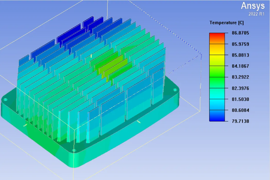
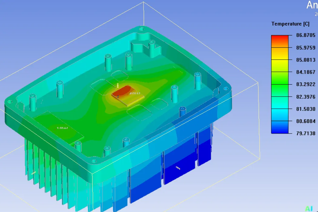
Without heat pipes, a high-power chip creates a “bullseye” thermal gradient: a very hot center surrounded by cooler, inefficient metal. With embedded heat pipes, this dynamic changes completely:
- Uniformity: The heat pipes effectively “short circuit” the thermal path. Measurements often show a temperature difference (ΔT) of less than 2-3°C from the center of the heat pipe to its ends, even over lengths of 200-300mm.
- Fin Efficiency: Because the heat is delivered to the edge fins at a high temperature, the temperature difference between the fins and the ambient air is maximized. This maximizes the natural convection velocity (chimney effect), potentially increasing total cooling capacity by 20-40% compared to a solid base.
Engineering Insight: Strategic Layouts
Embedding heat pipes is not random; it requires strategic placement to match the heat source location and the fin geometry:
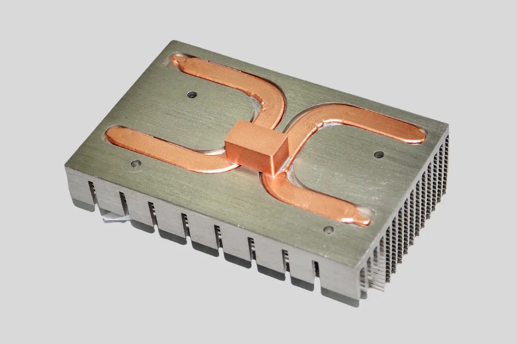
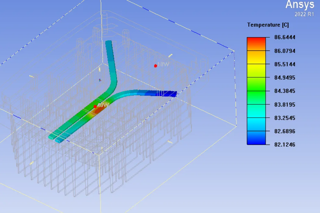
- U-Shape & L-Shape: Bending heat pipes allows them to pick up heat from a central source and distribute it to two or more sides of the heat sink simultaneously.
- Proximity to Source: The heat pipes should be embedded as close to the heat source as possible, often directly underneath the mounting surface, to minimize the initial conduction path through the aluminum.
- Groove Fit: To ensure performance, the interface between the round pipe and the square groove must be minimized. We use thermally conductive epoxy or soldering to eliminate air gaps, ensuring the bond line thickness is controlled to within 0.05mm.
Design Rules: Optimizing Heat Pipe Heatsinks for Natural Convection
Adding heat pipes is only half the battle. For a passive heat sink to function correctly in an outdoor environment, the geometry of the aluminum heat sink itself must be optimized for natural convection. Natural convection forces are weak—driven solely by air buoyancy—so the design must minimize airflow resistance while maximizing radiation. A heat sink designed for a fan (tight fin spacing) will fail miserably in a passive application.
Passive cooling design is fundamentally different from active cooling. Key optimization rules include using wider fin spacing (>6mm) to prevent boundary layer choke, orienting fins vertically to aid buoyancy, and applying high-emissivity finishes like black anodizing to maximize radiative cooling.
Fin Spacing and Geometry
The most common mistake in passive design is placing fins too close together to “increase surface area.” In natural convection, air forms a boundary layer on the surface of each fin.
- The Choke Point: If fins are too close (e.g., 2-3mm), these boundary layers overlap, choking the airflow. The air becomes stagnant, and cooling stops.
- Optimal Spacing: For effective natural convection, fins should be spaced at least 6mm to 10mm apart. This allows the warm air to rise freely, creating a strong “chimney effect” that pulls cool ambient air in from the bottom.
- Fin Height: Taller fins provide more area but increase air resistance. A balanced aspect ratio is critical.
The Role of Thermal Radiation
In a forced-air system, radiation is negligible (<5%). However, in a still-air, natural convection environment, thermal radiation can account for 20% to 30% of the total heat dissipation. This makes surface finish a critical performance factor.
- Raw Aluminum: Shiny, bare aluminum has a very low emissivity (~0.05), meaning it is a poor radiator of heat.
- Black Anodizing: Anodizing the surface black increases emissivity to >0.85. This simple change can lower component temperatures by 3°C to 5°C in outdoor applications just by improving radiative heat transfer. Ceramic coatings can offer similar benefits with better weather protection.
Orientation & Gravity
Outdoor telecom units (like RRUs) are typically mounted on poles or towers. The orientation of the heat sink is dictated by this mounting:
- Vertical Fins: The fins must be oriented vertically. If a heat sink is mounted horizontally, the fins block the rising air, reducing cooling efficiency by up to 50%.
- Heat Pipe Orientation: Heat pipes must work against gravity in some orientations. Therefore, sintered powder wicks are mandatory. They provide the high capillary force needed to pump fluid vertically, ensuring the heat sink works whether the unit is upright or tilted.
| Design Factor | Optimal Specification | Reason |
|---|---|---|
| Fin Spacing | > 6 – 8 mm | Prevents boundary layer overlap; allows natural airflow. |
| Surface Finish | Black Anodized | Maximizes emissivity (>0.85) for radiative cooling. |
| Fin Orientation | Vertical | Aligns with buoyancy direction for maximum air velocity. |
| Heat Pipe Type | Sintered Wick | Ensures operation regardless of gravity/mounting angle. |
Key Applications in Telecom and Outdoor Power
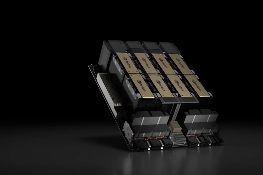
The transition to 5G and the decentralization of the power grid have created a massive demand for high-power, maintenance-free electronics. In these sectors, heat pipe embedded heat sinks have become the definitive industry standard. They are the enabling technology for 5G RRUs (Remote Radio Units), outdoor Small Cells, and Battery Energy Storage Systems (BESS), allowing engineers to cool loads exceeding 500W passively within sealed IP65/68 enclosures where fans would be a reliability liability.
Engineering Insight: In a typical 5G Active Antenna Unit (AAU), the Power Amplifier (PA) board generates intense heat. Without embedded heat pipes to spread this load, the aluminum housing would need to be 3x thicker to achieve the same thermal spreading, making the unit too heavy for tower installation.
5G Base Stations (AAU/RRU)
The shift from 4G to 5G Massive MIMO has drastically increased power consumption. A modern 64T64R AAU can generate heat loads ranging from 600W to over 1,200W. This heat is concentrated in the Power Amplifier modules.
- The Challenge: The unit must be lightweight for tower mounting and completely sealed against rain and salt fog.
- The Solution: Large die-cast or extruded aluminum housings are used, with 4 to 8 sintered heat pipes embedded directly under the PA chips. These pipes rapidly transport heat to the far edges of the fin array, ensuring the entire surface area of the unit contributes to natural convection cooling.
Outdoor Power Supplies & Inverters
Grid-edge infrastructure, such as telecom rectifiers, solar string inverters, and EV charging modules, faces similar constraints. These devices often operate in ambient temperatures of up to 50°C with full solar loading.
- Reliability First: Active fans are the most common point of failure in dusty environments. By using heat pipe embedded sinks, manufacturers can guarantee a 10-year service life without maintenance.
- IGBT Cooling: Heat pipes are routed from the high-power switching components (IGBTs/MOSFETs) to the external fins, keeping junction temperatures below 125°C even under peak load.
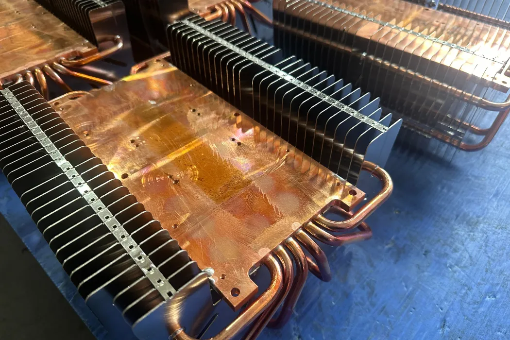
Walmate’s Fabrication Process: Precision is Key
The performance of an embedded heat pipe sink depends entirely on the quality of the interface between the pipe and the aluminum base. At Walmate Thermal, we use a rigorous manufacturing process to minimize contact resistance:
- CNC Grooving: We machine precise grooves into the aluminum base with tight tolerances (±0.02mm) to match the heat pipe geometry perfectly.
- Bonding Technology: Depending on the application, we use soldering (for highest conductivity) or high-performance thermal epoxy to bond the pipes, eliminating all air gaps.
- Fly-Cutting: After embedding, the mounting surface is fly-cut to achieve a flatness of < 0.05mm per 100mm. This ensures perfect contact with your PCB or power module, maximizing heat transfer efficiency.
Frequently Asked Questions (FAQs)
1. Do heat pipes work if the outdoor temperature is 50°C?
Yes, absolutely. A standard copper-water heat pipe functions effectively as long as the heat source is hotter than the ambient air. The working fluid (water) operates efficiently up to internal temperatures of ~200°C. However, a high ambient temperature of 50°C reduces the total thermal budget (Delta T), making the high efficiency of heat pipes even more critical to keep component junction temperatures below their limits (e.g., 125°C).
2. Can solar radiation stop a heat pipe heat sink from working?
Solar loading (approx. 1,000 W/m²) adds significant heat to the enclosure but does not stop the physics of the heat pipe. In fact, embedded heat pipes help mitigate solar hotspots by rapidly spreading that external solar heat across the entire thermal mass of the sink, preventing localized overheating on the sun-facing side.
3. How much more efficient is a heat pipe embedded sink vs. solid aluminum?
In high-power applications with concentrated heat sources, an embedded heat pipe assembly can lower component junction temperatures by 15°C to 30°C compared to a solid aluminum heat sink of the exact same size. It effectively reduces the thermal spreading resistance of the baseplate by over 90%.
4. Will the heat pipes freeze in winter (-40°C)?
Standard water-based heat pipes will freeze at 0°C. In a frozen state, they do not actively transport heat, acting only as solid copper rods. However, once the electronics turn on and generate heat, the fluid thaws and operation resumes. If active cooling is required during a cold start at -40°C, alternative fluids like Methanol must be used.
Conclusion
Passive cooling is the benchmark for reliability in outdoor telecom and industrial power, but aluminum alone has reached its physical limits. As power densities climb, the “thermal bottleneck” of conduction prevents standard heat sinks from utilizing their full surface area. Heat pipe embedded heat sinks are the engineering solution to this impasse, unlocking the full potential of large passive arrays by creating a near-isothermal base.
Success in this field requires more than just adding pipes; it demands a holistic design that optimizes fin geometry for natural convection, maximizes radiative cooling, and ensures a precision interface.
Don’t let thermal spreading limits compromise your outdoor equipment reliability.
Walmate Thermal specializes in manufacturing high-performance embedded heat pipe assemblies for the telecom and outdoor power industries. We optimize fin geometry, heat pipe layout, and surface treatments to guarantee reliability in the harshest environments.Contact our engineering team today for a thermal simulation. Let’s build a solution that stays cool under the sun.